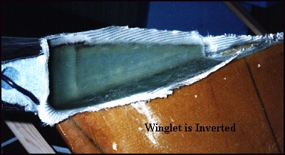
Remember, way back in the beginning...the winglets were the first items to be fabricated and stored away. Now, it is time to install the little boogers. First off, the bottom section of the winglet and the outboard tips of the wings are removed according to the airfoil templates. This allows access to the interior and underside of the wing and winglet skins. There will be massive lay-ups in these areas and eventually a cavity for the rudder horn...but I get ahead of myself.
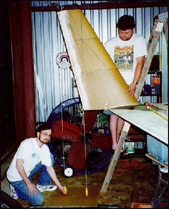
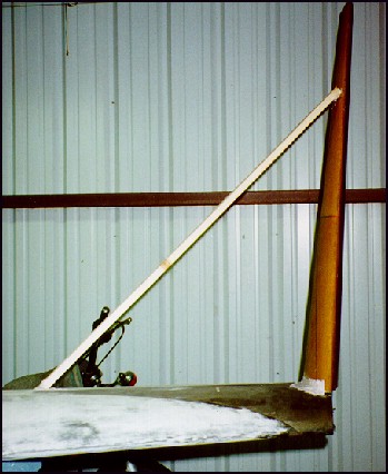
A point of the wing is established called the WPRP (Winglet Position Reference Point). This is the measuring point for the leading and trailing edge of the winglet. The WPRP is reproduced exactly on both wings and cross checked with triangulation references and distance from centerline. Once the proper alignment is marked and re-checked, the winglet is supported with a wooden strut and frozen in place for bonding with a generous helping of Bondo. The bonding process is quite interesting with all the interior skin plys and cross-connected compression plys. These winglets are built up even further from the Long-EZ specs (and those were stress rated at 145MPH lateral 'direct sideways' speed!!)
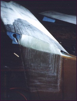
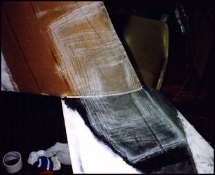
Once these monsters are stuck in position, it is time to bond them to structurally bond them to the wing. The first of many internal lay-ups is a 10-ply internal section from the underside of the upper wing skin to the inside of the winglet skin. These lay-ups are difficult to align but allow the winglets to be attached with incredible compression strength. Once semi-cured, foam bits are added to fill the gaps for the next 10-ply lay-up covers the interior foam cut outs and attaches to the flox corners and the new internal plys. More foam is then used to form a ramp for the 11 exterior plys to transition from the outside side of the winglet to the underside of the wing skins.
There is a similar 11 ply UNI lay-up on the inner side of the winglet to the upper wing skin. Clean it up, let it cure and get ready for the rudders.
Note: Be sure to catch-up by reading the section on the rudder installation as this update takes place after the rudders have been cut out and hinges and lever have been installed.
Some 7-years after originally installing the winglets, I am FINALLY completing the installation - the wing tips and lights. As you will see in this section, this was an exercise in 'sculpting' and was a challenge for me to complete....I'm no sculptor.
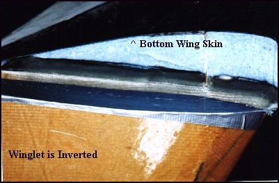
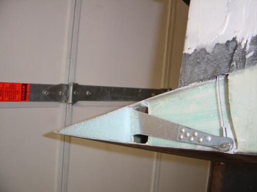
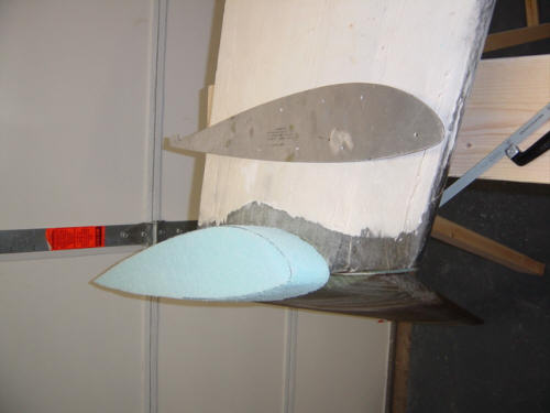
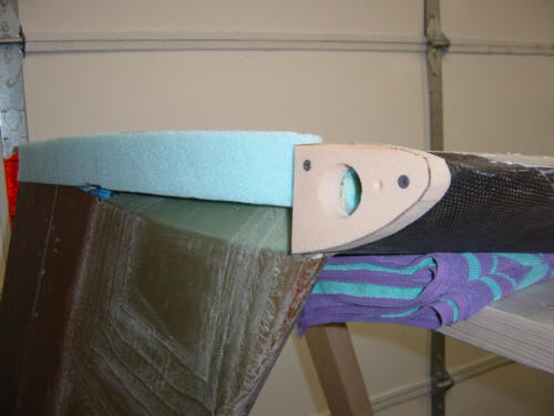
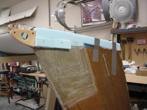
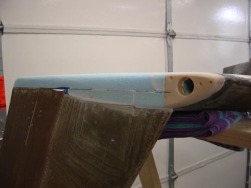
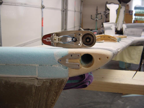
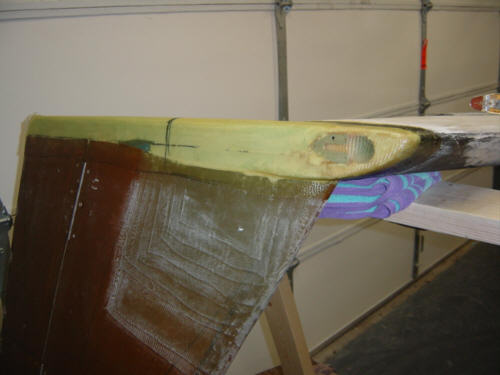
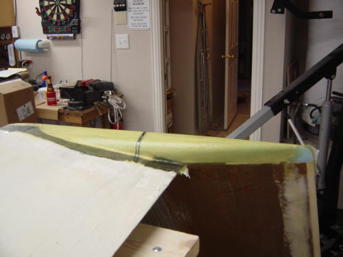
First, I installed the rudder cable into the existing Nylaflow tube in the wing and attached it to the rudder bell horn. A small piece of foam was also installed on top of the bell horn in the rudder cavity to make the surface level. I then pulled out a long forgotten (and dust covered) lower winglet template and cut out a foam block that becomes the wingtip core. The bottom of the block was slowly trimmed away so it would fit snuggly against the inner winglet structural plys and high density PVC foam was attached to the leading edge - together they will form the bottom of the tip. Smaller blocks of foam are contoured and installed with micro in the remaining gap between the winglet and the foam template. Once cured, the tip foam is cut down and sculpted to final shape. Dealing with all the multiple compounding angles was difficult for me to master, but all turned out very well. Sandy lent a watchful eye - looking for dips or wiggles in my sculpting.
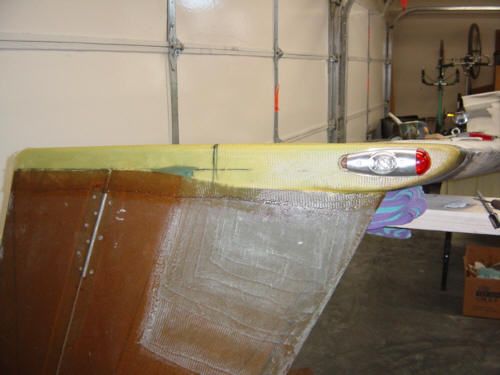
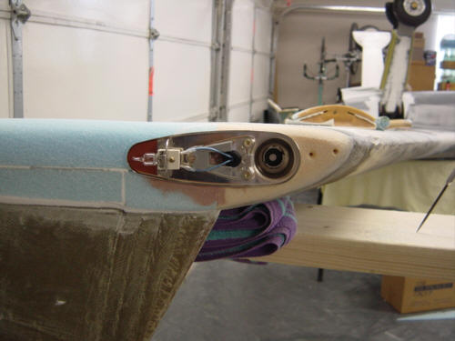
The lights were the easiest to install, in my opinion. As you can see in the picture above, I'm using the Whelen combo light (Nav/Strobe/Position) units. I started the installation by manufacturing and installing an aluminum mounting plate. The plate is mounted with Bondo and the light unit is attached for a trial fit and to check alignment with the waterline.
The actual wingtip structure is no more than 2-ply of BID and structural epoxy covering the whole assembly and lapping 1-inch onto the wing, winglet and rudder. A small section of the rudder's trailing edge is left un-glassed. After initial cure, the foam will be removed, replaced with a little flox and a 2-ply BID cover. This will make the lower rudder tip (a high-bump factor position) almost bulletproof.
 Back to the Proto-page