Updates:
7.) Kudos to iCom!!!
8.) NEW Trio EZ-Pilot Autopilot Install
9.) NEW Trio EZ-2 Altitude Hold Install
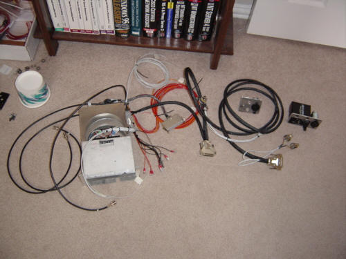
Now that most of the avionics hardware has finally arrived and has been bench-tested, I have started mounting the individual components to the metal frame. This process looks simple enough, but is turning out to be very tedious. There are several critical variables that all inter-relate - spacing, alignment, level, relative position, mounting bracket clearance, attachment hardware type, etc.etc. I, without a mill or any precision machining equipment, am doubly challenged. I can certainly tell you now why those avionics guys charge so much for panel work - any they DO have all the cool tools!
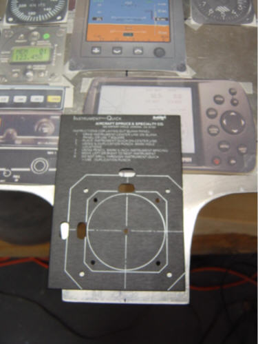
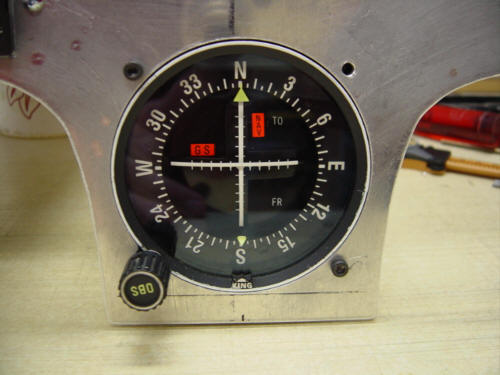
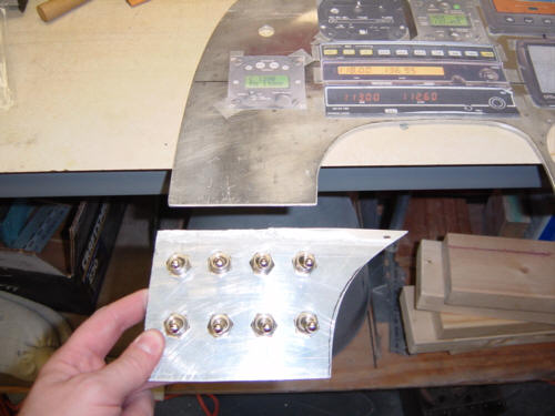
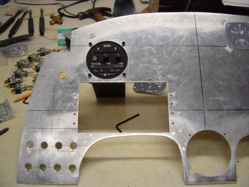
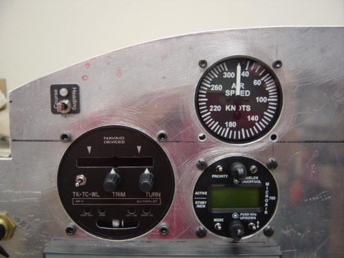
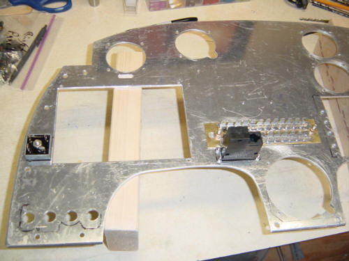
OK, enough whining, here we go. I do have a small ace up my sleeve - a $10 instrument cut-out template that I got from Aircraft Spruce. It's worth becomes exponentially important the further you go along. I started out with the KI-204 indicator hole (working from the bottom - up, and middle - out), using the template and an adjustable circle cutter. The template made drilling the mounting screw holes a snap, and the results were great!. Switching gears a little...(pun intended), I made a mock-up of the panel switch lay-out using a simple 1-inch spacing - it fit perfectly. I tested the clearance of the switches inside the fuselage and once I was happy, I marked the positions on the panel. I did not drill them at this point because I was still a little fuzzy on the bigger job that was next!
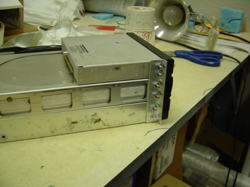
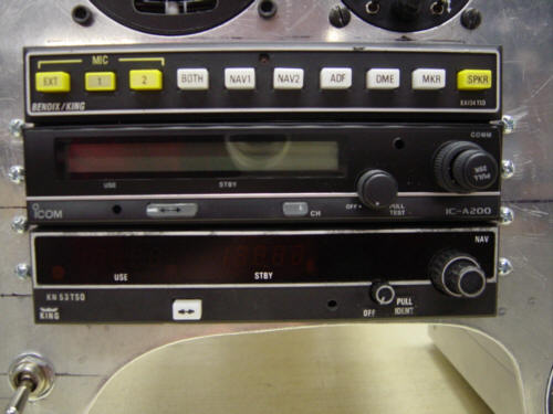
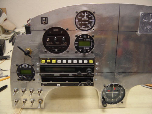
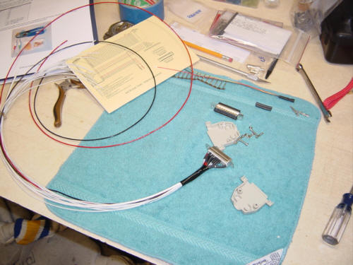
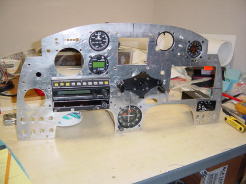
When I had the used instruments bench tested by Dick Ferguson of Ferguson Avionics, I took the opportunity to ask lots of questions about the radio mounting - spacing, mounting techniques, etc. That was a BIG help! So after a few trips to the hardware store for the right screws and things, I was able to correctly align, space, and secure all the mounting trays together perfectly! Thanks, Dick! Once I measured...measured...and measured again, I masked off the cut-out area and used a jig-saw to set it free. After a little filing for final fit (say that 3-times fast), I had three radio trays mounted in the panel (KA-134 Audio Panel, iCom A200 Transceiver, and a KN-53 NAV+GS receiver)! Whew!...I was really sweating that.
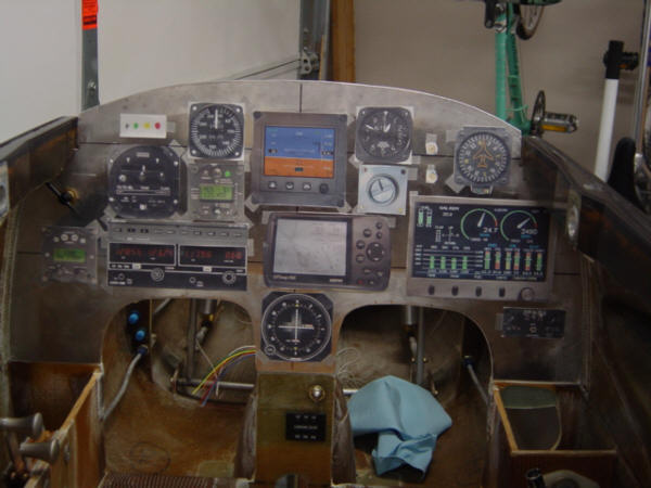
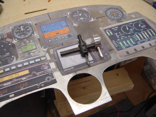
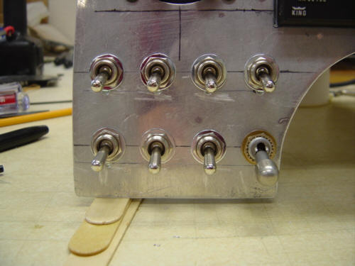
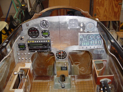
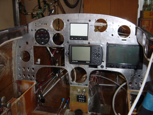
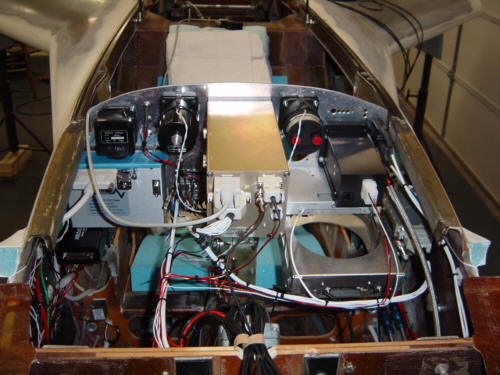
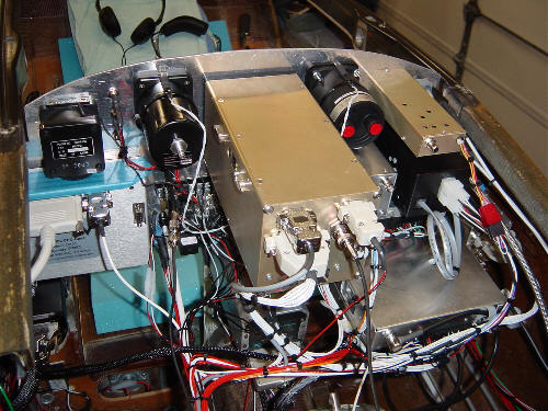
Now...back to drilling the switch holes. After verifying that there was still no interference, I drilled the switch holes and the small reliefs for the anti-rotation washers - they also turned out great. The remaining holes followed the same process as the first one - NavAid Autopilot/Turn Coordinator, Microair T2000 Transponder, backup Airspeed Indicator and the Microair 760 Transceiver. Of course, the big picture looks something like this. The back of the panel is starting to look impressive too. I decided to go ahead and mount the panel by trimming the fuselage mounting flange and creating the mounting tabs and holes. In the process, I just could not wait any longer to drill and install the right side switches as well...What can I say, I was on a roll and I can now say I'm half way there.
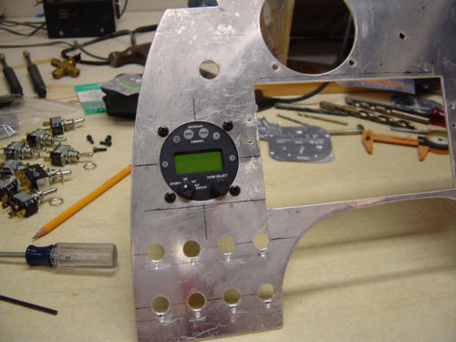
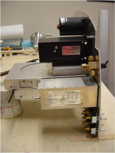
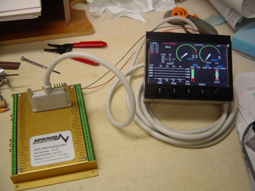
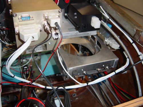
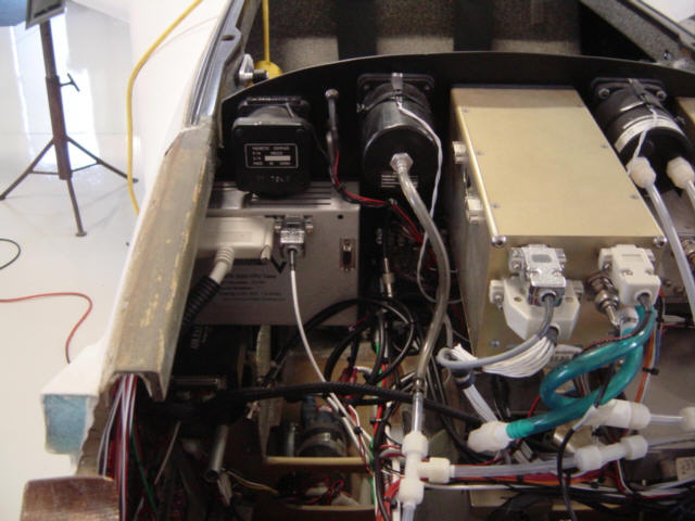
The next panel session involved installing the WAY nifty-kewl Advanced Control Systems ACS-2002 engine monitoring unit. Of course, the data processing unit is mounted in the aft section of the aircraft, and only the display is mounted in the panel. Let me tell you, this thing is a work of art...Rob and Ken really paid attention to the details! It even ships with its own cut-out and drilling template. This basically made it the easiest of all the instruments to mount. Line it up, center punch the holes, mark the lines, mask it off and then cut and drill...it was that easy. After that monster hole was cut, I moved on to the vertical card compass and altimeter mounting holes that are just above it. Those were pretty standard to I will not bore you with the details.
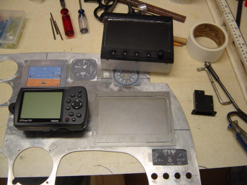
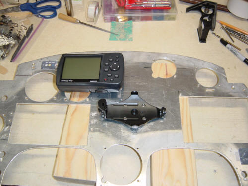
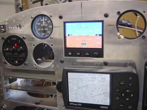
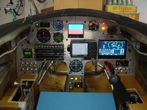
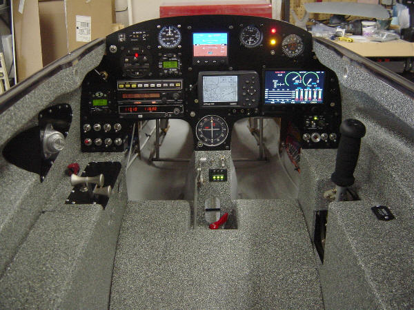
The Garmin 196 presented the biggest puzzle. I am abandoning the idea of mounting it flush in the panel - just too much work for the reward. And, because it now mounts almost 2-inches forward (rather aft) of panel, its placement is a little awkward. Because of parallax, I had to install the mount as far up the panel as possible as not to block the view of the NAV indicator. I had to mock-up seat cushions to raise my eyes to the level they will actually be during flight. From there, I was able to verify the correct position to install it. You will note the picture at the top of this section is shot from a lower angle and the GPS looks a little out of place - it isn't...just the parallax messing up the shot. The asymmetric mounting did allow for some really trick additions - I was able to install and hide the screw heads for the panel ground bus block on the other side of the panel and tuck the ELT remote head in under the GPS (it's in the shadow of the GPS from the viewing position so I don't have to stare at it all the time). I am thinking about also tucking a nose gear breaker under there too...just to keep it out of site, but still accessable in a pinch. You will also note in that last picture, I installed the Essential Bus power diode to the panel - this is due to it needing a heat sink for the amount of power flowing through it. What better heat sink that that big honk'in metal instrument panel. ;-)
With a few weeks left until the EFIS-Lite and intercom arrive - it was a perfect opportunity to sit in the cockpit, play with the switches and fly around the hanger. REALLY! I must have logged 3hrs of workshop flying time pushing buttons, flipping switches, and running scenarios on the panel...let's call it "ergonomics and system research time".
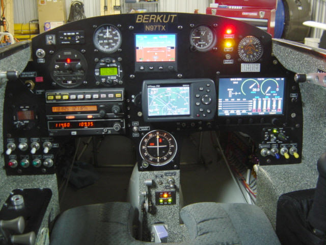
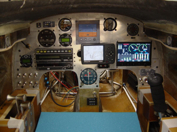
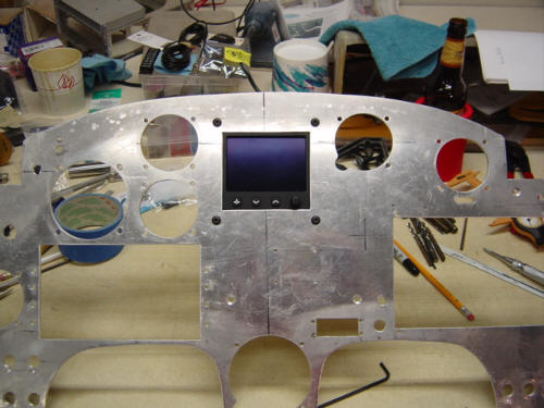
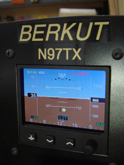
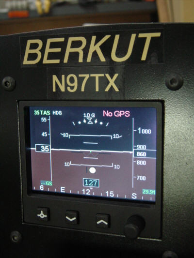
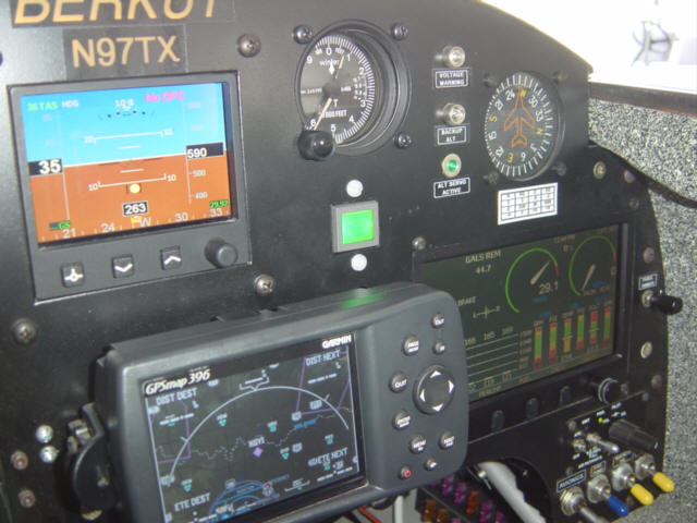
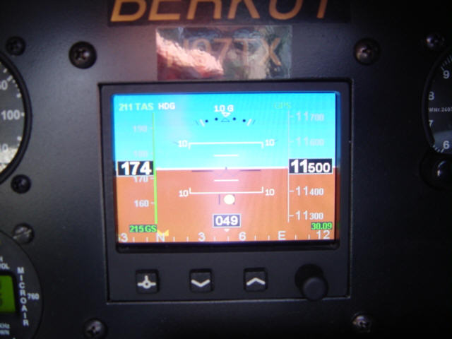
Update 11-28-03: It's here, it's installed, it's calibrated, and it is beautiful!! The Blue Mountain EFIS-Lite is the center point and crowning jewel in my panel. In my panel it is tasked as the primary pitot/static/gyro flight attitude and direction instrument and feeds altitude information to the transponder. I have to say, this thing is another computerized work of art....Greg Richter and crew really did a good job. So, here is how the installation went:
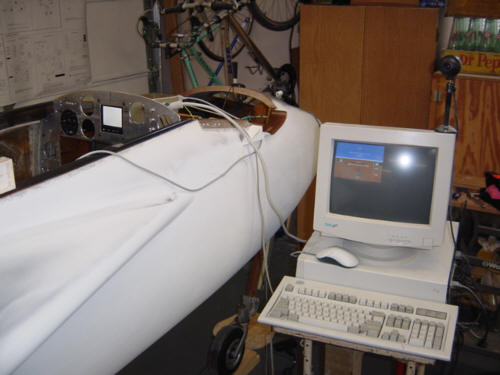
First objective was to get it mounted. Because the unit is self-calibrating, it is immune to panel tilts of up to 10-degrees, and slightly non-level mounting is also not a problem. However, because I'll be staring at this thing for the next 20 years, I was especially careful with the installation. Cutting was hole was not as easy as they mention in the manual - the diagrams and so-called templates do not print full scale so you are left to measure and create your own template based on unit itself. But, after a few hours of careful re-measuring, drilling and filing - I did manage to get it mounted very nicely in the panel. Once back into the leveled fuselage, it was calibration time. I rolled the web-cam system over to the fuselage and hooked up the EFIS-Lite to the monitor and keyboard and booted it up. Calibration was as simple as pressing the 'L' key and EFIS was almost ready to go. I hooked up the OAT probe (Outside Ambient Temperature) and installed it in the nose gear compartment. The EFIS uses it to calculate True Air Speed - a handy function to have easily displayed. I also soldered up the altitude encoder data wire harness and ran the wires over to the MicroAir T2000 Transponder. I fired it all up, set the transponder to 'Display Altitude" and there it was...they were talking to each other at last!
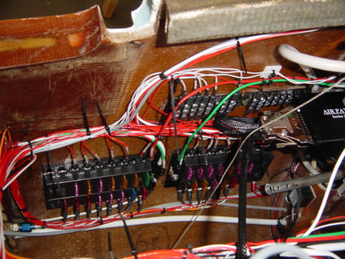
A few more power and data connections later...and the back of the panel is getting pretty dense. But now, the GPS is talking to the AP-1 autopilot too. I also installed the panel instrument dimming and lighting (notice the blue-ish glow around the airspeed indicator). I'm loving this stuff - next up....the radios!
Update 11-30-03: I have most everything on the panel up and operational except the radios. After much debate, I have decided to have the avionics shop do the radios. It will be a simple job for them, and the biggest benefit is the ability to BENCH TEST all of it before it gets installed in the plane - greatly complicating any required changes or repairs. So, in the interest of 'doing it right the first time', I have the panel stripped down and ready to transport to the airport. (sigh) I really hate parting with it...but it is for the best overall.
Update 12-14-03: Boy, I'm glad I had that does by the pros. There were several "undocumented" items with that King stuff. Those install manuals sure don't make it easy...and alot of information is left out. If I had done it myself, I'd have no idea how to hook some of that stuff up. It all came with a price too...about $950...and that included parts, labor, testing and several troubleshooting calls to fill in the gaps in my brain. Even with the radio harness 99.5% complete, I still had alot of work to do integrating the new systems into the wire bundles, power distribution, intercom cable runs and TROUBLESHOOTING. Yep...nothing is perfect...but that is what 'experimenting' is all about. Anyway, the front side of the panel has become much more complex and only a few fuse slots remain empty. After hooking up one of the winglet antennas, I had my first conversation with an aircraft flying over - totally exhilarating! ...now, back to sanding.
A little more to come here as I get the remaining systems on-line - Nav lights, strobes, and ignition! I'll have to paint the thing too - semi-flat black is on the top of the list (for ultimate instrument contrast and minimal intra-cockpit reflections).
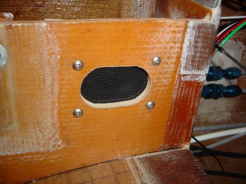
Update 1-30-04: I originally was going to leave this off of the plane, but there it was...a wire that didn't go anywhere or do anything. I just could not stand it any longer...it HAD to do something. I broke apart one of my old sets of crappy computer speakers, gutted it and tried the speaker out. Well, it was crap then...and it is still crap today! So, I logged on to www.mouser.com and bough a little oval 2"X2.75" 8-ohm, 5-watt speaker for a whopping $3. This time...it sounded GREAT!
I mounted the speaker in the left pilot's console and cut an oval hole in the bulkhead. Left over from by now dissected computer speakers was some metal speaker grill material - I cut it down to size and painted it black. Mounting was simple - 4 screws and presto...the cabin speaker was mounted.
Keep in mind, this speaker is just for ground use. I can listen to the local Unicom traffic, weather reports, or tower chatter while I preflight the plane. I think it will come in handy someday...and was worth the few hours of work.
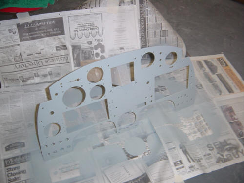
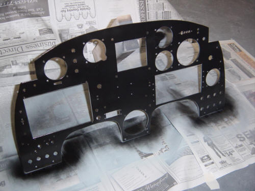
UPDATE 5-1-04: Now that I am finishing up the interior, I have removed all the instruments from the plane and have painted the panel. This puppy is looking good now. I was going to have the panel plate powder coated, but I ran out of time and money...had to go cheap...but good. So I polished the aluminum with a scotch-brite pad, sprayed on the primer, and shot it with semi-gloss black. I chose black fro two reasons - to reduce the glare in the cockpit as much as possible, and to provide the maximum contrast to the instruments.
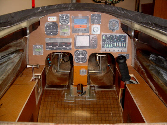
UPDATE 5-6-04: Here are a few pics of the finished front cockpit - front seat, left console and panel close-up (before the labels were added).
UPDATE 7-18-04: I was taking some pictures of the changes I was making (shown in the Interior section) and I shot some pics of the EFIS Lite mod that Greg made for me. I was trying out the systems in the dark one night and noticed that the EFIS was way too bright and the dimmer didn't do enough. Greg told be how to modify the dimmer to make it a little more effective, but it was still too bright. So, he made a "night mode" by changing the color palette. So, now I can have a nice bright color for day and a dark color screen for night ops. It worked great! Thanks, Greg!!
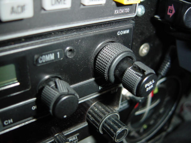
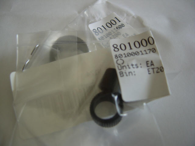
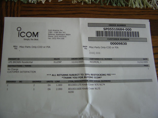
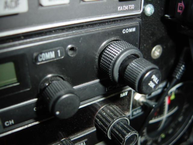
UPDATE 12-5-05: I wanted to take the time to document a very rare happening - Amazing Customer Service! As you know, I have a iCom A200 radio as my primary Com1. It's only been in operation for 1.5 years, but the rubber grips on the knobs are ALL becoming brittle and cracking. A couple have actually cracked and fallen off. This is primarily a cosmetic thing, but it does affect the radio's operation. Just on a lark, I went to the iCom website, and submitted a support request describing my problem. I mentioned that the plane was hangared, and was not exposed to large amounts of UV light. The next day, I received an email response asking for my mailing address so they could send me replacement grips - no questions asked. I was shocked! But, to my amazement, a set of knob grips came in the mail. Not only that, but at no charge what-so-ever! So now, the replacement grips have been installed and it looks as good as new. Now THAT is great customer service! Kudos, iCom! Kudos!
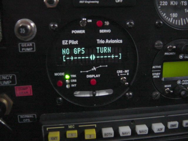
UPDATE 12-5-05: After the thrashing we endured during this year's AirVenture Cup race and the fact that the NavAid controller was of no help at all - I decided to invest in a more capable autopilot. I selected the Trio Avionics EZ-Pilot unit. It uses the same servo as the NavAid, but has a solid state inertial gyro like the EFIS does. It only tracks on GPS (no provision for VOR) but does it very accurately and is smart enough to workout intercepts and multiple waypoint tracks. I've only tested it a couple of times now, but my initial tests indicate that it is right on the money! It is completely superior to the analog NavAid, tracks and intercepts smoothly, and although I have not had it in more than lite turbulence, it damps out those bumps very quickly. It was by far the easiest avionics install I have ever performed. I literally unscrewed the NavAid control head, installed the Trio in its place, and connected the pig-tail adapter cable to the existing connector. That's it...it worked perfectly right out of the box! Great job Trio!!!
You can read more about the Trio Avionics products on their WebSite.
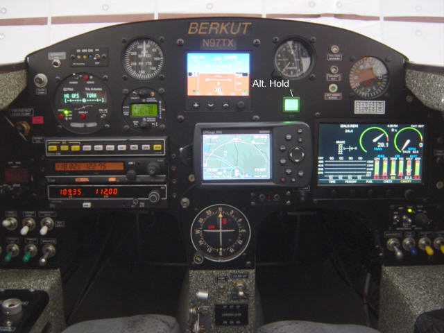
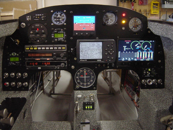
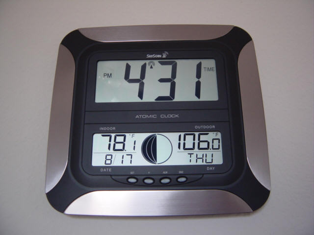
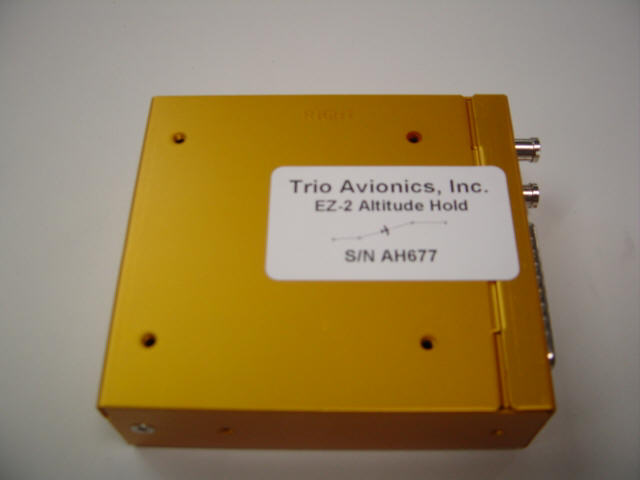
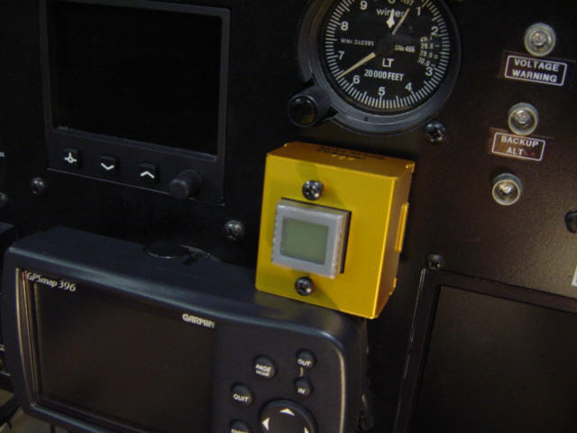
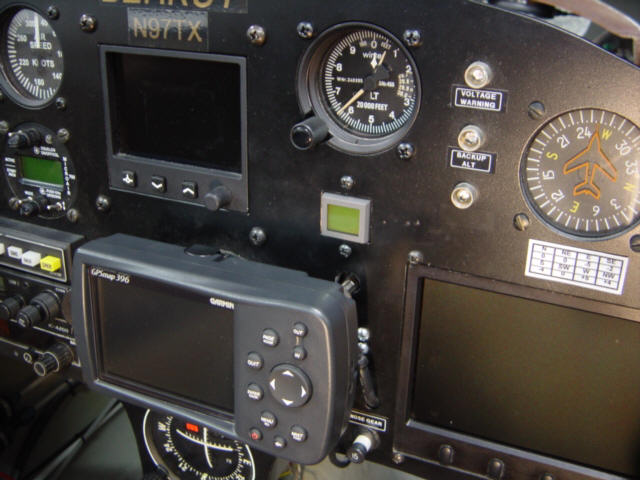
UPDATE 10-8-06: Well, I finally got around to installing the last of the panel avionics - some two years after first flight. I have to admit, this additional was purely optional, but something I consider a requirement for single pilot IFR use - altitude hold. The only other Berkut's I know of with this feature installed the S-TEK 2-axis autopilot and spent a boat-load of money doing it. The S-TEK AP a great system if you can afford it, but the servos are big and heavy, the head unit is big and bulky, it does not have half of the features that the Trio has, and did I mention it's expensive. In my big panel plan, I had reserved a little space below the altimeter to accommodate something...and as it turns out, I was just the perfect spot for the EZ-2. I had been following the development of the Trio products, and at this year's Oshkosh (2006) I stopped by the Trio booth and Jerry Hansen gave me the full demo. Wow! They have come a long was from just a "push the button to lock altitude" unit...and I bought one right there on the spot and had it shipped back home. I knew I was going to have the plane disassembled for annual inspection when I got back so I planned to do the install then. The only "problem" with having to do the annual inspection on my plane is that it currently comes due in August...in Texas...when it 106 degrees outside. Man, I really need to re-set the inspection clock to sometime in say...February. ;-) Anyway, I toughed it out, drank lots of water, and get it done.
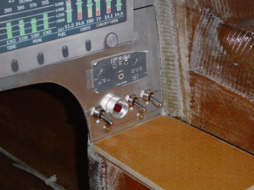
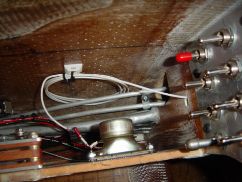
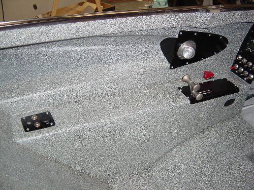
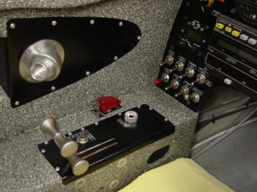
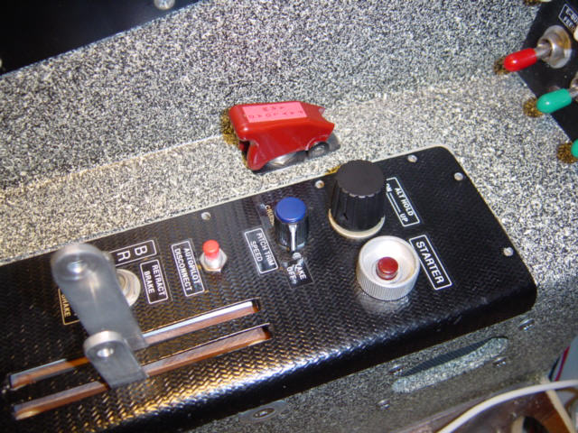
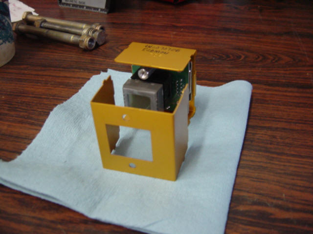
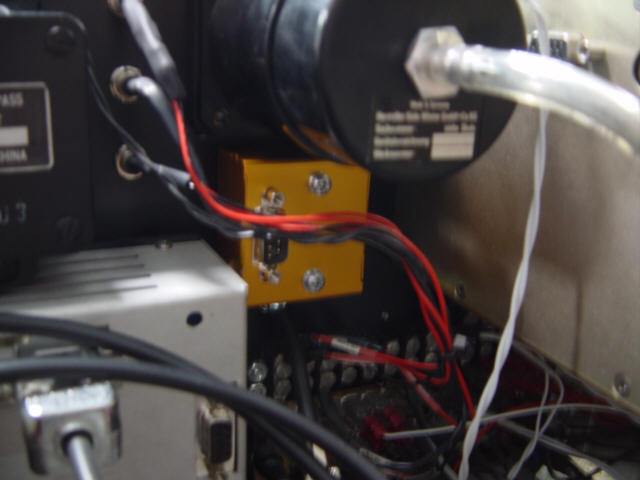
It is obvious to me that the creative "brains" behind the EZ-2 designed the unit to conserve panel space and allow a variety of installation options for us "tandem" folks that are perpetually short on panel space! Thank you, Trio! The unit is of modular design and comes as four separate components - brain-box, display/control button combo, selector knob and the servo. As you can see, these components can be installed practically anywhere and allows the builder to "fit" the components into the cockpit however they choose. I really like this feature, as it not only saves space and makes it EZ to install, but it also allows the components to better fit the ergonomics of the panel and control systems. As a general rule, my cockpit design puts all the items that require manual adjustment or input on the left side of the aircraft (where my free-hand is). So, in following with my ergonomic design, I installed the selector knob on the left throttle console within finger's reach. This knob is used to select climb/descent rates or speeds, adjust up/down for pressure changes in flight, and to adjust settings as required. Once the unit is engaged, this is really the only thing that you adjust during flight. I also put the alt hold servo disconnect switch (INSERT PIC HERE) on that console as well. Note that it is a different type of switch (momentary toggle vs. push button) than the autopilot...this is so I can tell the difference tactilely and not have to look down to select the correct switch. That's it...1/4 of the install is complete. How simple can you get?
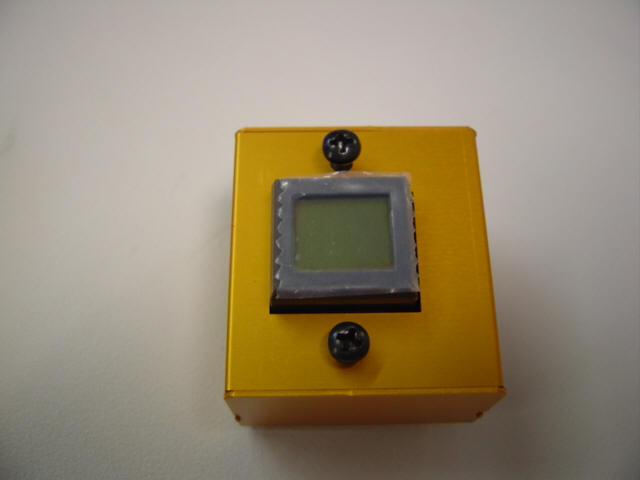
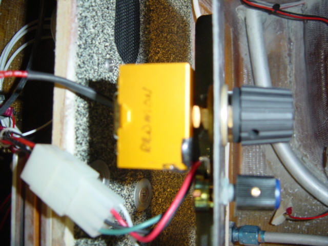
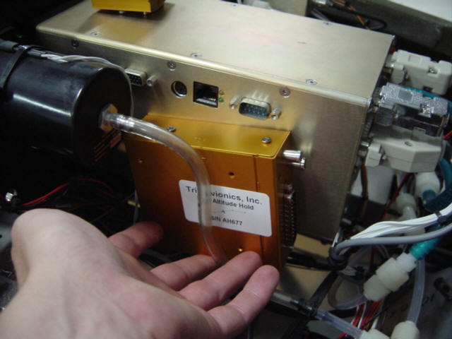
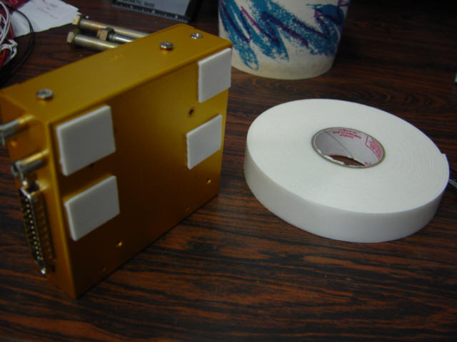
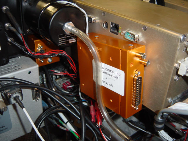
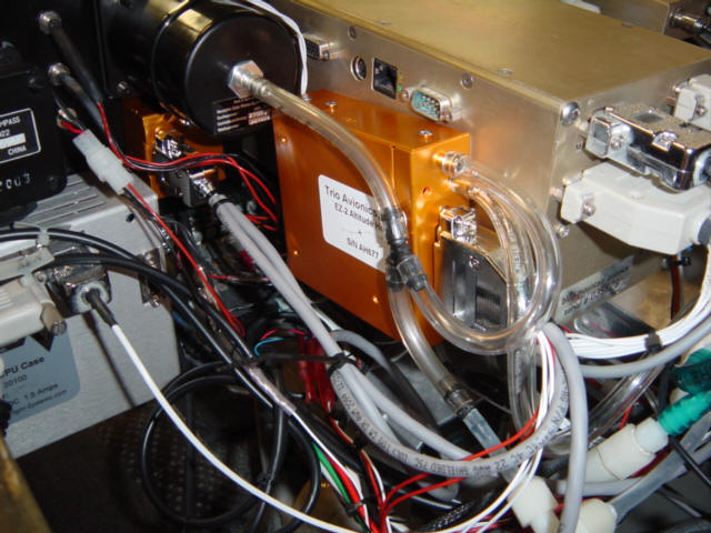
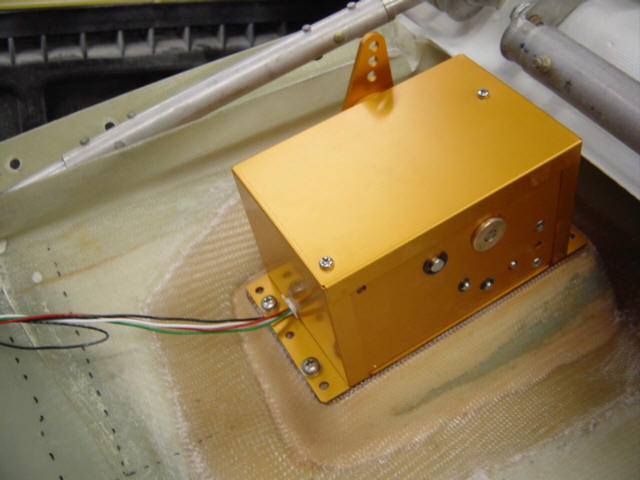
Next up was the brain-box. It contains a solid state rate gyro in it, so it is the only component that has to be oriented correctly during installation - basically just make sure that the "right side" of the unit is facing the "right side" of the aircraft and that it is generally level on the top. However, the unit will auto adjust for fine adjustment if the unit is not perfectly level - or even installed up-side down, I'm told. The front of my panel is a little crowded but I found a good place to mount the unit. All I needed to do was attach it to the side of the EFIS unit with a few strips of double sided tape. The unit only weighs a few ounces, and the tape not only provides a stand-off for cooling, it help isolate vibration. So, ta-da, now 1\2 of the system is installed. While I was at it, I tapped into the existing pitot and static lines and plumbed them to the ports on the EZ-2 brain-box. Now, on to component #3...
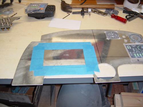
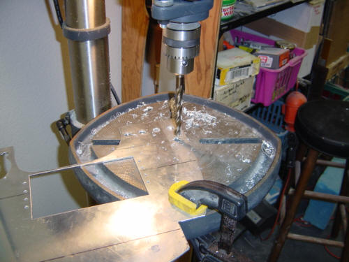
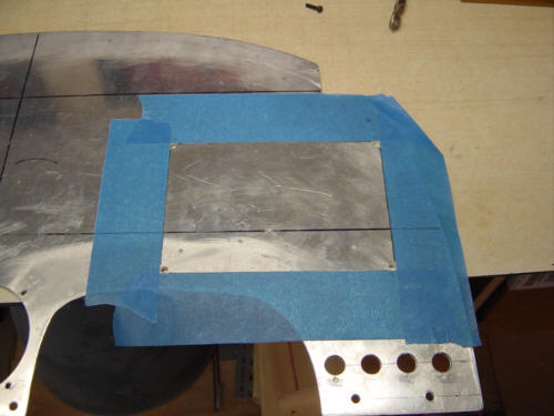
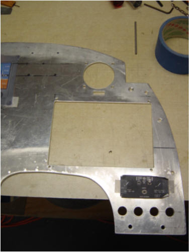
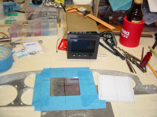
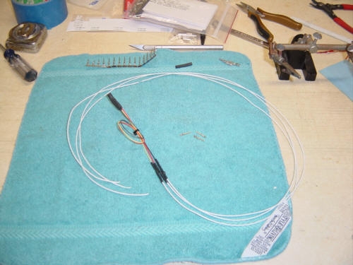
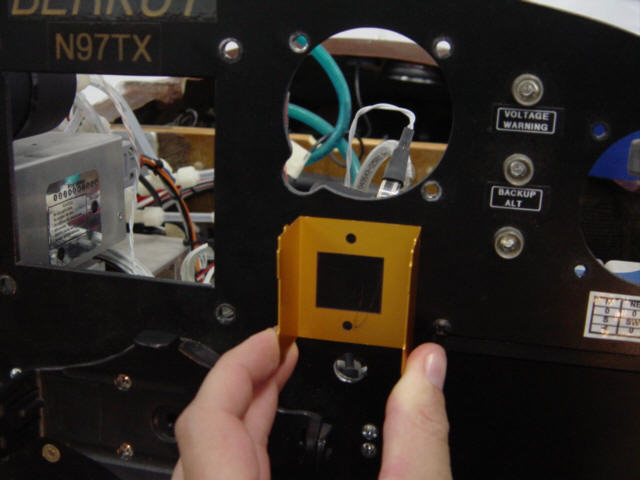
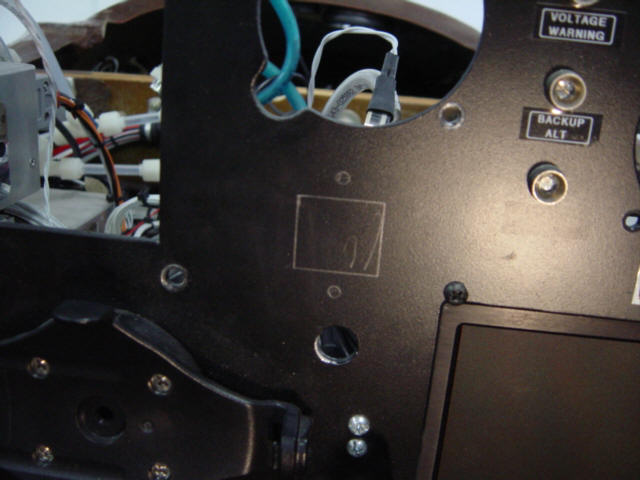
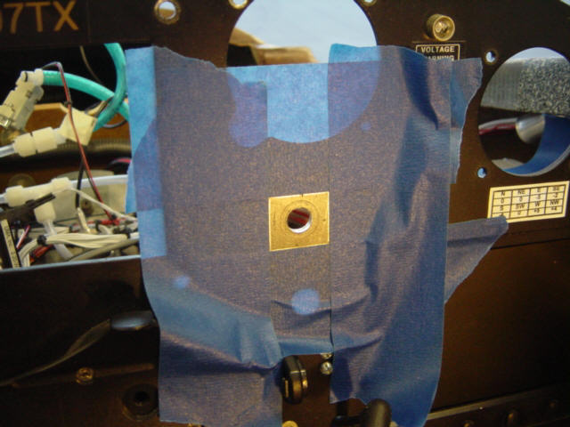
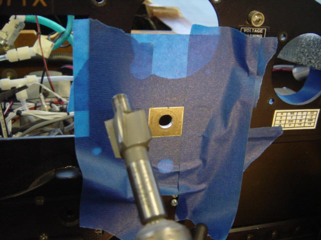
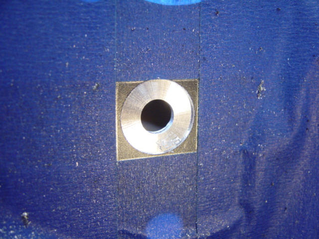
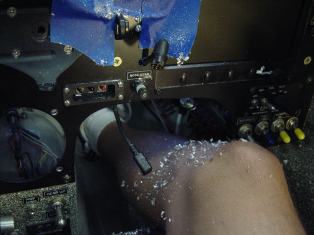
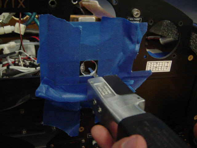
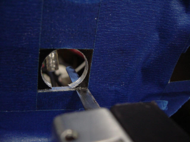
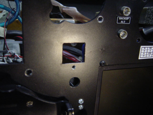
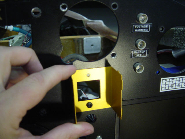
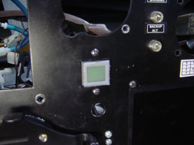
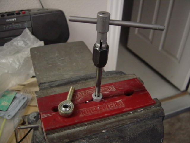
The next item was a little tricky...and scary to install since it required cutting a hole into the existing metal instrument panel. Yikes! But it has to be done. As I mentioned before, I had a little panel space reserved for this and as it turned out, it was just enough space to fit the display button and its case. I removed all the sensitive instruments from the panel to protect them from the heavy vibration, and steeled myself for what came next. With so little space to spare, correct positioning was very important. I carefully removed the cover from the display and used it as a template to mark the exact location of the cut-out. OK...fingers crossed...here it goes! I used painter's tape to mask off the area and drilled a pilot hole in the center of the cut-out. OK...I'm committed now! Then used a counter bore bit to cut the majority of the material away. Because this was a very sharp bit, it cut through the hardened aluminum easily and reduced amount of vibration quite a bit. However, it was quite messy work. So, how do you make a round hole square? With a power tool, of course...but very carefully!!!! When I was all finished, I used some small files to smooth the edges and a black sharpie to darken the bare metal. Whew! It actually turned out great...but I still have more holes to drill. I drilled the lower hole where it had been marked and then used the case again to precisely locate the upper hole. No adjustment was required, and a few screws later - the display button was installed. I got the location just right too - you can see here how tight the fit from the front of the panel. Man, am I glad that's over...but it looks like it really belongs in that space. Next up, I fabricated the shielded multi-conductor wires that connect all the parts together. This was really simple exercise with soldering connectors and following a simple schematic...no biggie there. Yeah, 3/4 complete now but it's REALLY hot at the hangar, so luckily...I can take the next part home and work on it in the air-conditioned shop.
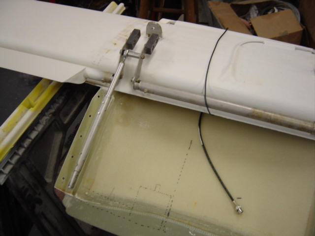
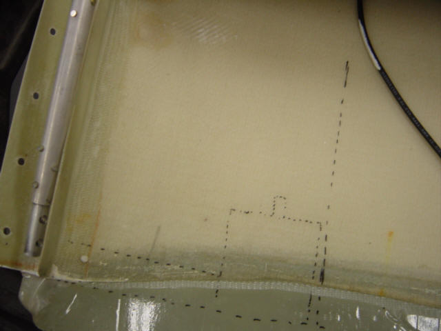
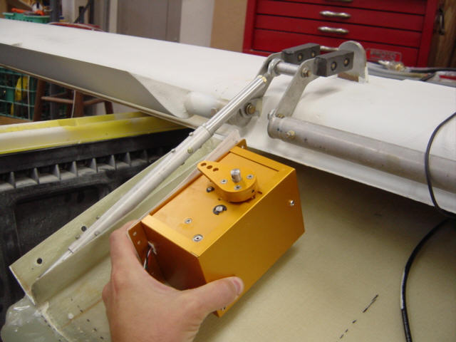
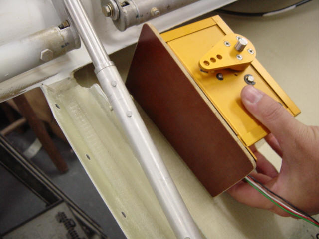
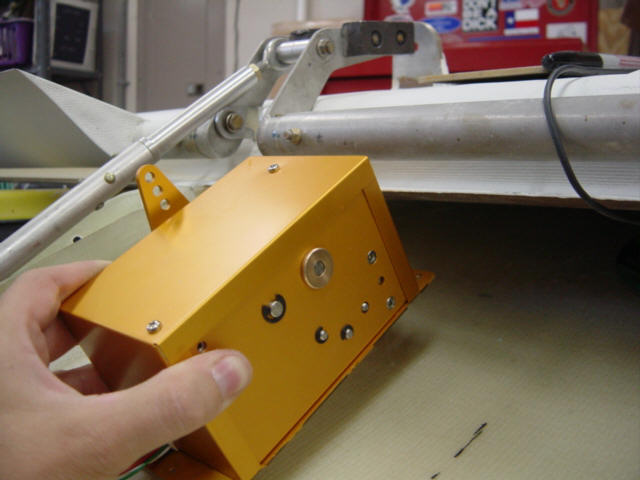
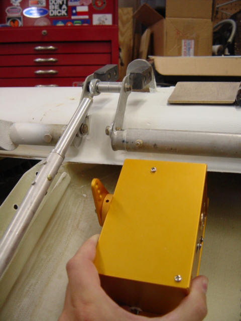
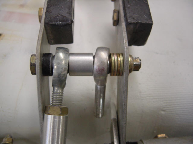
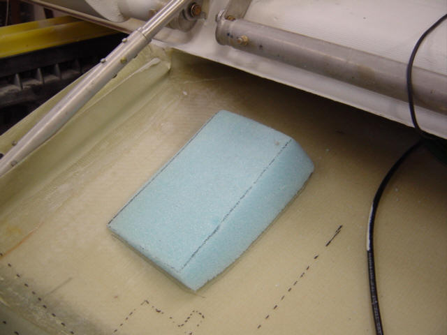
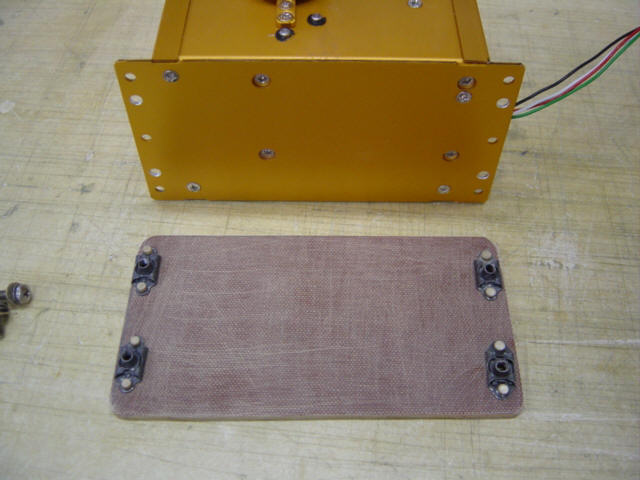
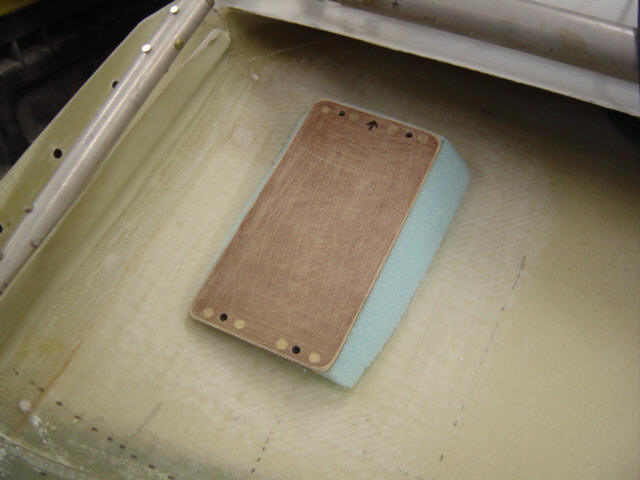
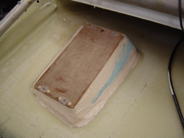
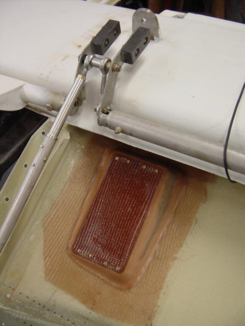
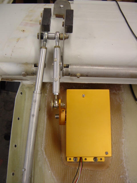
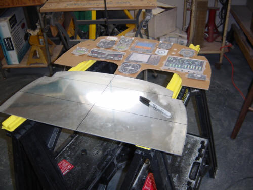
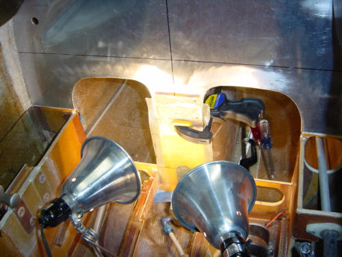
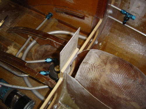
The servo itself looks and operates just like the roll-servo of used with the EZ-pilot autopilot, but the electronics inside are a little different. It needs to be installed somewhere along the elevator control system in an orientation that allows movement in a single axis. On the Berkut, the best place for it is mounted to the upper canard cover and connected directly to the elevator bell crank. Before bring the canard to the house, I measured and marked the panel instruments shadows on the canard deck so I would know what space was available for the servo. I certainly didn't want to install this thing only for it not to clear the back of some instrument. As it turns out, I had plenty of room...I just had to choose a servo mounting style and orientation. My first idea was to mount the servo on its side to a single phenolic plate that would be bonded to the canard deck - very simple. This would have worked, but the arc of the elevator bell-crank would have resulted in lots of side movement on the rod-ends...so, I scrapped this idea. The slightly heavier, but more reliable method was a straight forward install with the servo mounted normally which makes a straight connection to the bell-crank but requires the fabrication of a mounting stand. In fact, with that method, I don't even have to drill into the bell-crank...I can just install a rod-end directly to the cross member where the control stick push-rod attaches - all the better. Getting the foam shaped to the compound curves was not too easy, but I did eventually get it right. Since I would not have access to both side of the mounting bolts with this design, I had to install some nut plates to a phenolic plate for the servo attachments. Then match the mounting plate to the foam, fill the voids and edges with dry micro, and cover with 2-ply BID glass with at least a 1" lap and let cure. While that was curing, I had to re-drill and tap the provided push-rod insert to accommodate the larger rod-end for the cross-member attachment. A few hours later, I cleaned up the lay-up edges, opened the holes, and installed the servo. I had already double, and tripled checked the servo arm rotation geometry with the push-rod length and attach points, so all I had to do was bolt up the linkage. Bingo! One pitch servo installed with no binding or rod-end side-loads. All that's left now is turning the system on!
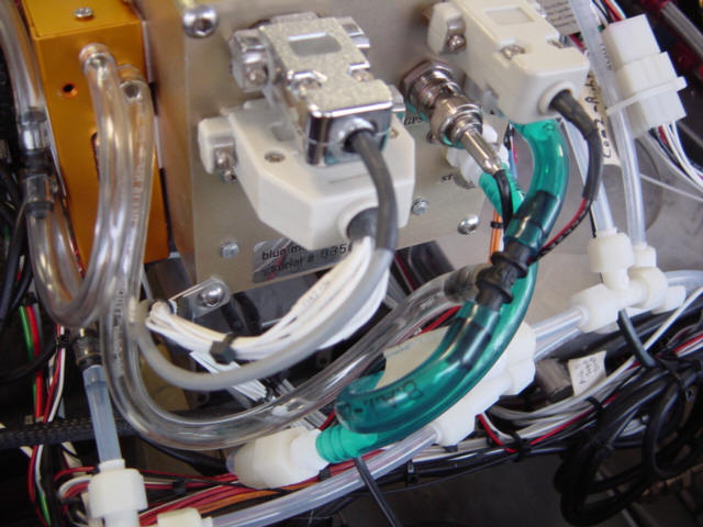
Back to the hangar I went with the canard. Re-installation went without a hitch, I plugged the servo into the rest of the system, installed the fuse, and powered it up. I was happy to see that the unit booted up properly and passed the self-test mode. I performed the calibration and direction tests, and determined that with my servo installation, I needed to change the direction of operation to "reverse mode" - this was because the servo arm was rotated 180-degrees for proper alignment. So, a few "clicks" later - was holding altitude on the ground. The unit was operating properly, but the only minor problem I encountered was electrical noise on the audio circuits when the servo was engaged. This was a result of a ground loop somewhere up on the panel (the panel itself is a common ground point for the audio equipment) unique to my airplane�s systems. This issue was easily solved by providing the unit with isolated ground and power from the aft buss closest to the main battery and isolating the wire shields from the nose/panel grounds. I did that by using Nylon screws and washers to insulate the display button case (white screws) from the panel ground. Once I determined this solved the problem, I replaced the ugly white screws with black plastic ones. No biggie.
So, how does it work - perfectly! It took a few test flights to set the sensitivity, servo dead-band, min/max airspeeds, and such. But this was a simple and easy process that was well documented in the instructions. The unit is full of features, but the main feature is still as simple as "pressing the button" to lock onto the current altitude. The first long cross country flight was to Rough River this year. Weather was nice, and I used the unit to climb at a stable 130kts to 11,500ft., leveled off and re-engaged to hold at that altitude (alt pre-select is now available with the EZ-3 upgrade). It never varied more than 15ft. the entire trip and I never touched the stick. I adjusted the alt for pressure changes enroute, and even set it up for a 300ft/min. descent to our destination. A great little workload saving unit!! Had this been an IFR flight, my workload would have been significantly reduced. But even VFR, I was now free to listen to XM radio, take pictures, eat a snack, enjoy the ride, use the porta-potty and all without having to fiddle with trim every 5 mins. Good job, Trio! Next time the canard's off, I'm sending the brain box back in to be upgraded to the EZ-3. Pre-select will be a nice feature to add, given the accuracy of the unit's operation. To summarize, the unit is easy to install, is feature rich, accutate and EZ to use - I highly recommend this product!
You can read more about the Trio Avionics products on their WebSite.
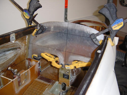
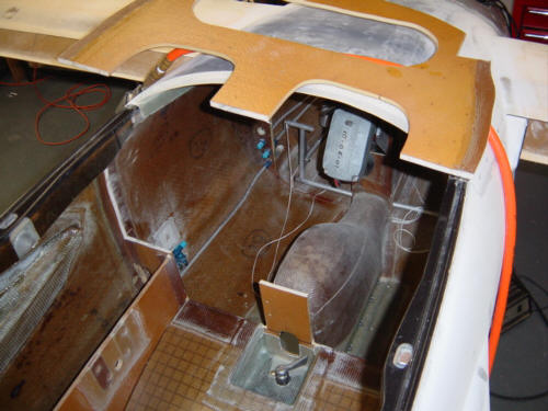
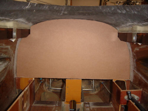
Now that the mock-up is the correct size and all the planed instruments fit in the allotted space - it is time to install the REAL panel frame. I used 1/8-inch thick 2024-T3 aluminum sheet for my panel. I used the cardboard from the mock-up panel to cut the aluminum to shape. This is a trial and error process of trimming and shaping the metal frame to fit perfectly inside the fuselage - this took several hours to complete, but it finally fit. The metal frame will be held in place by a 9-ply thick flange on the fuselage side walls. That process is detailed below.
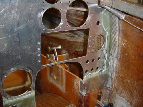
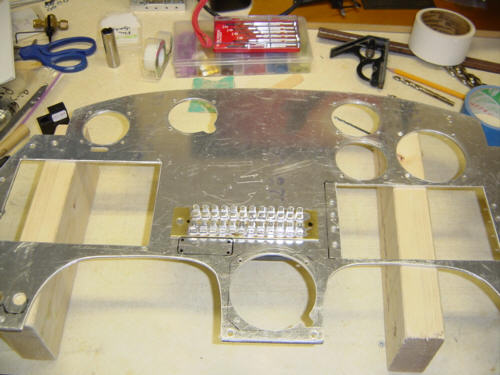
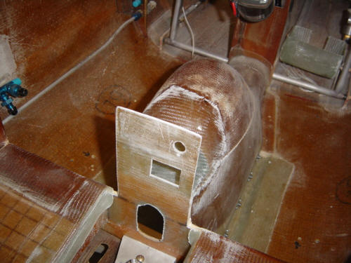
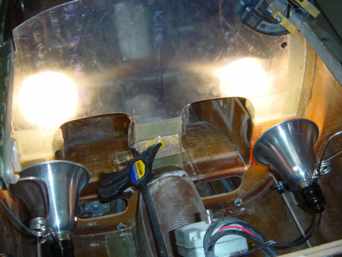
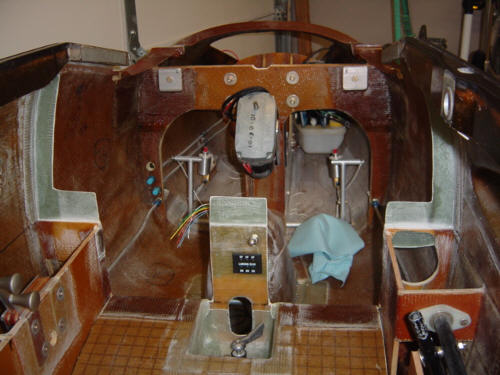
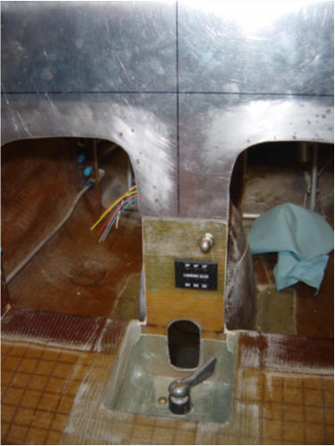
After moving the instruments around on the panel, I needed to re-position the gear switch and position indicators down in the center 'leg' of the console. This meant I had to do some modifications of the original structure. I first layed-up 3-plys BID to the aft face of the console to stiffen it up. Then I removed the foam on the forward side and also cut away a portion of the nose gear bowl to make room for the gear switch and indicator block. Before putting the thick plys on, I thought it would be a good idea to go ahead and position, cutout and drill the holes for these items - it made things easier in the long run. Now it's time to do the thick ones - 6-ply BID tapes are applied all around the sides and bottom legs of the panel. I used a full 9-plys on the center leg to keep it stiff. Once that is semi cured, release tape is applied to the panel, an additional 3-plys BID is attached to the aft side of the new flange, a flox corner is added around the parameter, and the panel is clamped into position. This squeezes the flox out of from behind the metal and make a nice crisp part-line.
When the flange is complete, it will look something like this. The gear switch and position indicator look like this when installed.
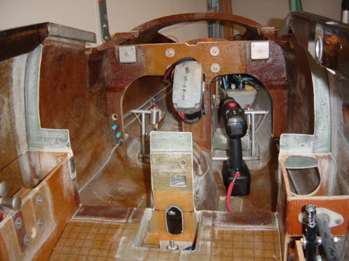
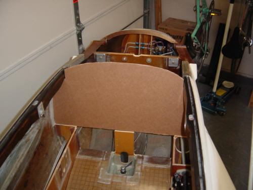
Here marks the first REAL work done on the instrument panel installation...to date, all the work has been in design and component selection. For the moment, I have the selection nailed down to the finalists...but the next several months could find something new coming to market. We will see...but for now - here it is. Way back when the fuselage bulkheads were installed, a fiberglass instrument panel was put in place as the one to use. Since then, just about everyone has gone to a removable, slanted, 1/8-inch thick, aluminum panel to make things more accessible, easier to read, and gives additional clearance for the top instruments and the canard deck drip rail. This is what I will be installing as well.
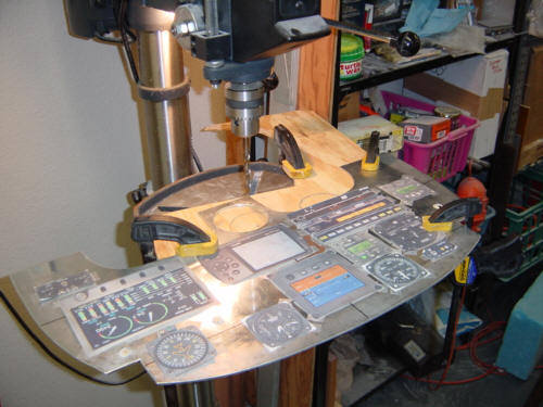
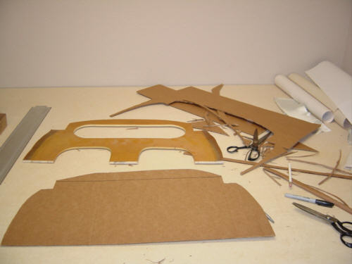
Before anything can begin, the old fiberglass panel must be removed. It's simply cut out using a long hack-saw blade chucked into a air-saw. Once removed and cleaned up, the old panel is used as a rough template for cutting a piece of cardboard to shape. The cardboard is trimmed horizontally until it fits perfectly in-between the fuselage walls. Then the front canopy is lowered so the top can be trimmed to fit as well. Now you have a rather sturdy template that the aluminum sheet can be cut from.
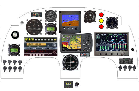
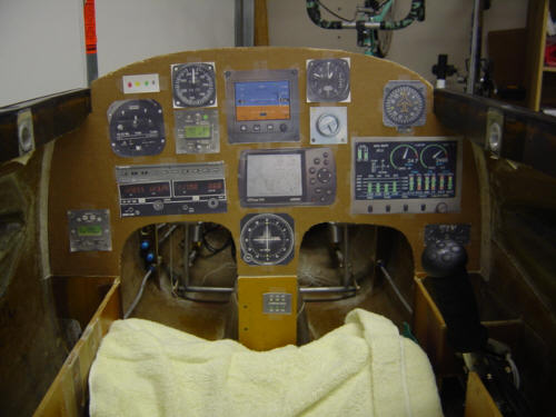
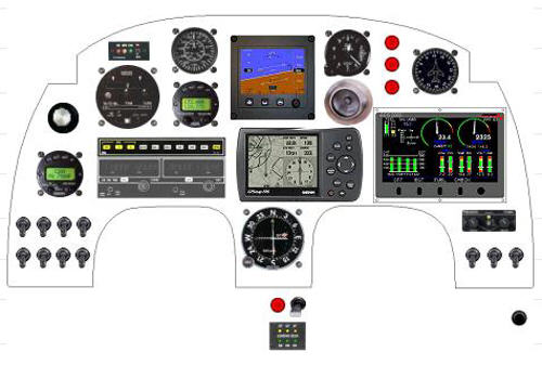
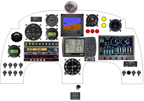
Here is where a little more technology comes in...along with some ingenuity: I searched the Internet and downloaded as many of the instrument faces I am using as I could find. If I had the item already (compass, Garmin196, vent, etc.), I just took a digital picture myself. Then used a graphics program to accurately size the image so that when printed on a color printer, it was the exact physical size of the real instrument. This allowed me to attach the color instrument cut-outs to the cardboard in the exact positions on the panel. This little trick not only let me verify that the placement of the instruments all worked out, but it makes the cockpit look SO much more realistic - I sat in there making engine noises for hours!! WAY FUN! Seriously, I had to re-position some of the item to make things a little more ergonomic and visable.
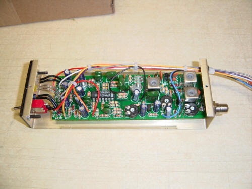
While taking a break from the sanding and filling duties, I tackled building the RST Marker Beacon kit...as if building the plane was not enough. First, let me say that the kit was top rate, the instructions were easy to follow and the final product was all I was expecting and more. A++ to Jim Weir and team.
It took me a solid 6 hours to read & understand the instructions, construct the unit and do the initial testing. Not bad at all. I was so absorbed in the building process, I forgot to take any pictures. However, here is what it looks like when completed. If you are in the market for a marker, I highly recommend RST's.
Some may think that I jest about the instrument panel, but really it should be viewed as one of the biggest decisions a builder has to make. Aside from the aesthetic appeal the panel will make in your airplane, what you put in it will determine what functions the plane will perform. And don't forget that a basic IFR panel like mine will cost you about $15,000 to $20,000 - so it is also one of the most expensive parts of the aircraft!
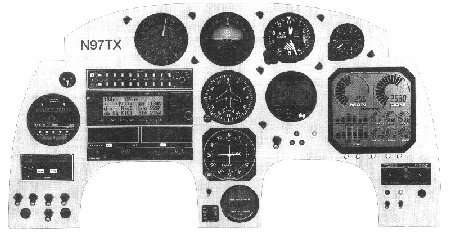
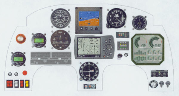
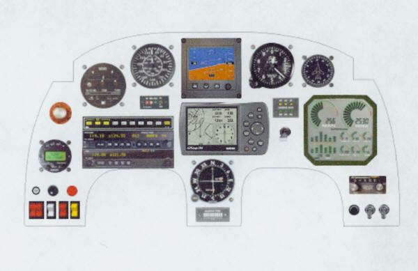
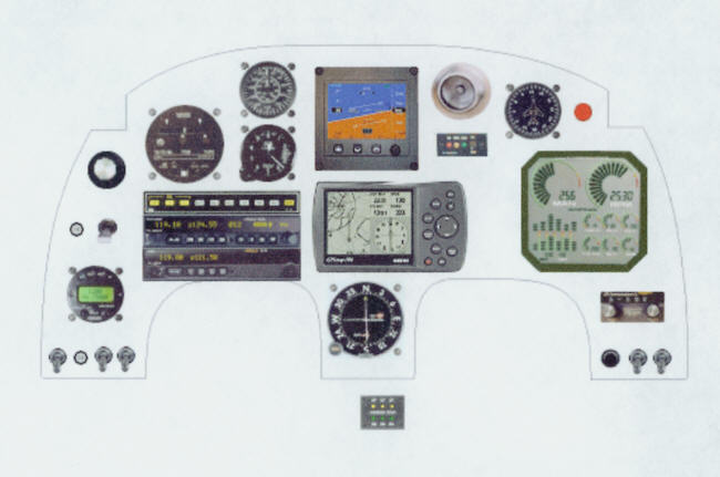
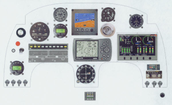
Previous versions were: Panel_A, Panel_B, Panel_C, Panel_D, Panel_E, Panel_F
The basis for my selection was based on these things:
1.) I wanted a basic IFR configuration with ILS
2.) I wanted two Com and two types of Nav radios for redundancy
3.) I wanted a GPS/VOR coupled autopilot
4.) I wanted to take advantage of the newer "glass panel" technology
5.) ...and I will NOT have a vacuum pump or system
My goals were very basic but I also wanted the panel to look very sharp as it would be the 2nd thing most air show visitors look at! I have put this one together and it meets all my needs as this point - it will still be a few months before I commit to an actual template. I don't plan to fly hard IFR in the Berkut but setup the panel so I could make precision approaches/departures as I plan to do extensive cross-countries. At 250MPH, and the gas mileage of a Honda....who could blame me?
Some of the major items are detailed here:
Blue Mountain Avionics EFIS-Lite - A real jewel of an instrument. It is self-contained and based on new solid state gyro-rate sensors...yep, no moving parts. It's LCD display shows a wealth of information in one spot..and really, everything else in the panel is backup. For more information, check out Blue Mountain's EFIS-Lite page. Yeah, it's the most expensive instrument, but it is the only one that keeps getting better over time!
Advanced Control Systems ACS-2002 - A combined color display is great for condensing all the engine monitoring AND warning information into one spot. The Berkut has panel space for most applications but this instrument cleans things up quite a bit! All of the main warning systems can be built into this unit (canopy open, gear, belly brake, etc.) and you get a text AND verbal audio warning to boot! No more annoying buzzer, flashing lights, or habit forming 'buzzer silence' button. A Data Processing Unit will mount in the rear turtle deck and probes will go through the firewall to the engine. A single ribbon cable connects the aft DPU to the panel display. It doesn't get any easier or better than this! And to think - I was originally against using this unit because I was not taking advantage of the fuel level or flap displays. In all - I think it is work a few extra hundred dollars for the warning system alone!
Navaid Devices Turn Coordinator/Auto Pilot - Again, here is yet another space saving instrument. It replaces the turn coordinator and is also a single axis autopilot. I can't afford a full, 3-axis, big-time S-Tek autopilot but this baby will track either a GPS or NAV course. So maybe now I'll get a little break up there in the clouds to change maps, frequencies....or underwear.
Garmin 196 GPS with moving map, partial panel, and HSI - Well, that about says it all. A panel mount GPS/Comm with moving map would have been much more expensive and has a smaller screen. It even has a backup battery pack in case of electrical failure. The features are too numerous to list here but they have a great web page on the 196. Check it out.
I just can't cost justify the UPS Slim-line radios I was looking at...so, back to originally going with a remanufactured King KX-155/209 combo. It's a solid, supportable, and affordable solution. I can get fancy once I win the lottery. ;-)
 Back to the Proto-page