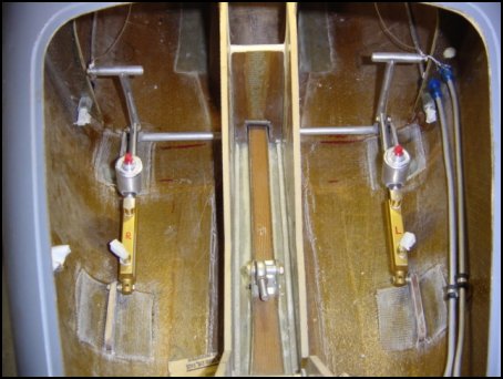
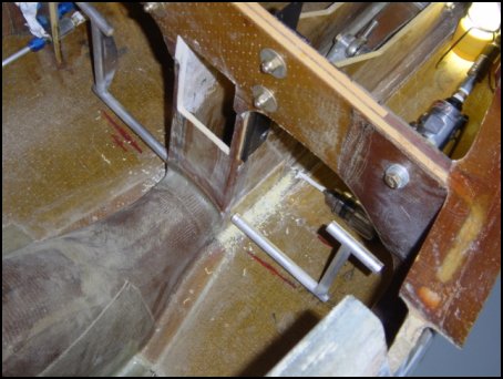
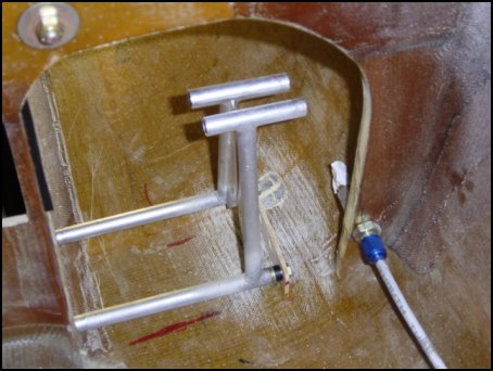
The rudder pedals are for the Berkut are very close to the recent Long-EZ implementations where the brake master cylinder is up front and not on the firewall. The pedals are attached to slip tubes that allow the first inch or so of pedal movement to actuate the rudders, then begin to engage the brakes for the rest of the travel. The completed mechanism looks like this.
You start by sitting in the plane and marking on the floor of the fuselage where your feet are at rest. Then based on that position, attach a 1/8-inch phenolic hard point to the side of the NG-30 stringers. Then several holes are drilled in the hardpoint to allow the pedal to be adjusted for, in my case, taller pilots. Once the pedal positions are established, you make another 1/8-inch thick phenolic tab for the outboard ends of the pedals. By using both pedals at the same time, you can be sure that the alignment of the tab is correct for all positions. The same method is used for the 1/4-inch thick phenolic mount point for the master cylinder - complete with the same four mounting positions. 2-plys of BID on each side of them all and you're done. Here is what it all looks like from the pilot's point of view.
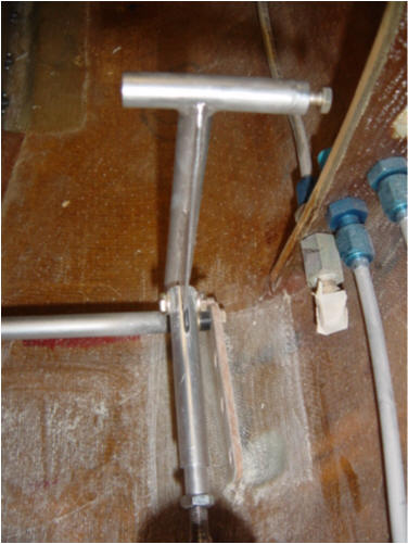
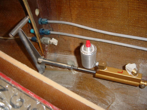
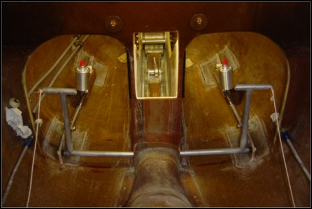
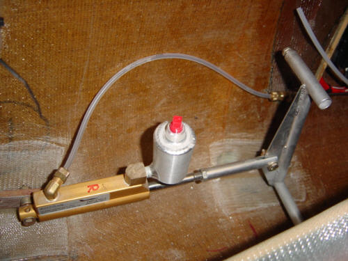
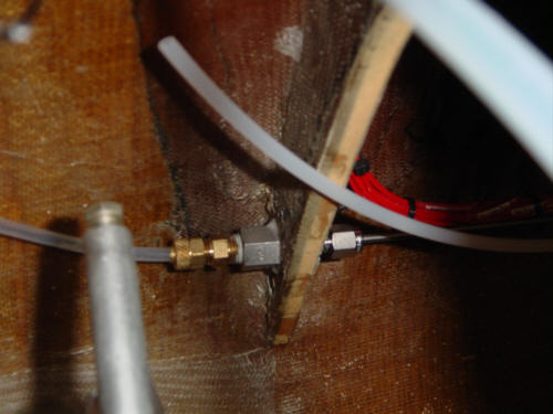
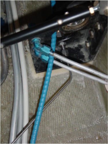
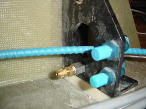
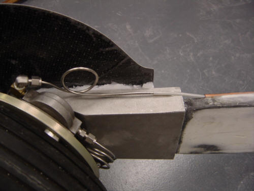
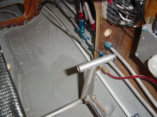
UPDATE 2-23-04: I never really put much up on this page regarding the brake system and several Long-EZ guys have asked about them...soooo, here is a little more info: The Berkut brakes are a little different from the original Long-EZ design but are directly adaptable to Long. As you can see from the above, the pedals depress the master cylinders after a little travel for the rudders. The master cylinders are connected to the fuselage hard lines using 3/16" Nyla-seal flexible tubing feeding into and out of brass Poly-flo fittings. This stuff is great - flexible, durable, chafe resistant, and doesn't harden much with temperature. The brass fitting plugged into a Swageloc bulkhead fitting and converted to 1/8" stainless steel lines that run down the side of the fuselage to the main gear trunions. I used to have 1/4" aluminum lines, but yanked them in lieu of the more durable SS tube system. The aft connection are the same - Swageloc bulkhead to Poly-Flo brass fitting, to 3/16" Nyla-Seal flex tube to the stainless tubing running down the gear legs the calipers. I even have a small run of SS tube inbetween the brake calipers. I hope this description an pictures are helpful. This would be an EZ retrofit over the Nylo-Flow based tubing used in the original plans. Have fun!
UPDATE 9-13-04: WARNING - DO NOT USE the 1/8" SS tubing that is available from Aircraft Spruce. It is .035 wall tubing that only has an I.D. of 1/16" - far too small and restrictive to allow stick-free brake actuation. The 1/8" SS tube needed must have a .025 or .020 thick wall to allow enough inner diameter for adiquite fluid movement on the return stroke. I didn't realize there was a difference in the 1/8" I ordered and used, but ended up having to replace the long fore/aft fuselage runs with Nyla-flow tubing temporaraly so I could continue with flight tests. Later, I will want to replace that line yet again with Nyla-seal or metal tubing...not a fun thing at all, but it happened. More details on this mod in the Post-Flight Squawks and Mods Section.
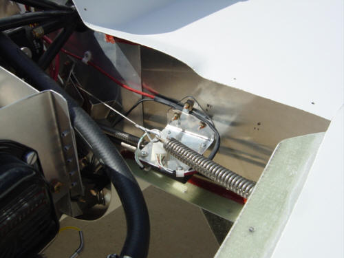
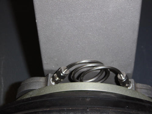
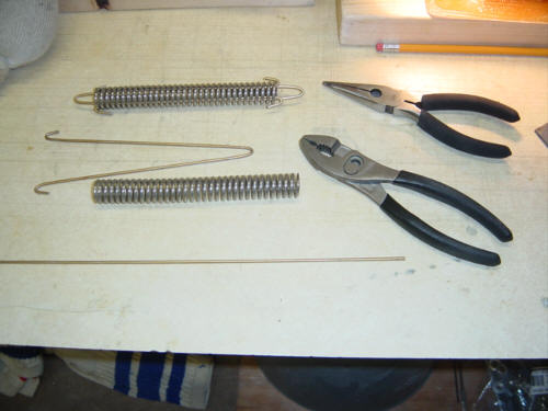
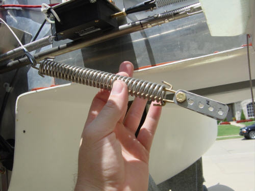
Now the pedals do something! I threaded the cables through the Nylo-flow tubing that was installed with the conduits and attached them to the rudder pedals with Nicopress sleeves and a cable thimble. Next up, I took some hinge rod and the rudder over-travel springs and shaped some pulls so that when the cable is pulled, it compresses the spring. This spring absorbs the over-travel that might happen when the rudder is at maximum extension and the brakes are engaged. They are installed in the engine compartment with a adjustment bracket so that the rudder pedals can be adjusted. When it's all done, you get something like - this.
 Back to the Proto-page