Well...I actually started with the aft end of the plane and I am working forward with the objective of laying down the initial power distribution system first. I am using the Z-12 (two alternator, one battery) electrical system as described in The AeroElectric Connection by Bob Nuckolls. This book is THE electrical bible for anyone building a homebuilt aircraft!! Thanks, Bob for all your help and for being a great teacher! What the design means is that I will have three redundant sources of power in my...all electric/no vacuum...airplane. The primary source of power comes from the main 60-amp alternator...large enough to power everything in the plane simultaneously. Should this fail, the secondary 20-amp alternator will automatically pickup the load for the critical systems. Lastly, if BOTH of those units fail, I still have battery power available to the entire system. To further extend battery-only time, the system incorporates an 'essential instruments buss' that can be isolated and powered directly from the battery. You just can just not be too safe with all those electrons racing around at the speed of light - and Bob's book makes it easy to boot!
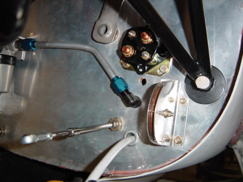
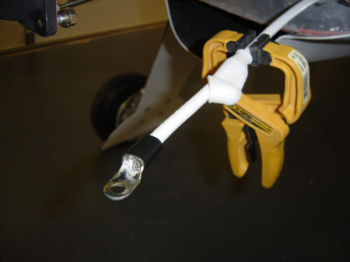
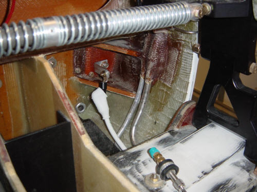
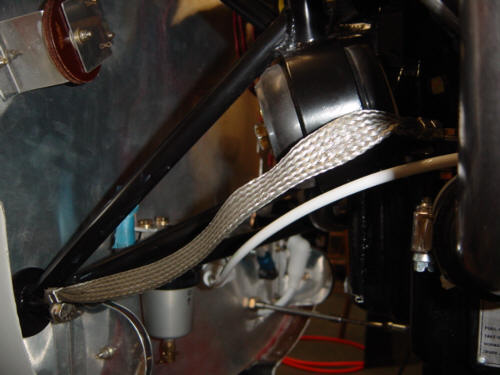
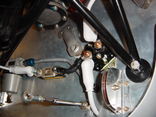
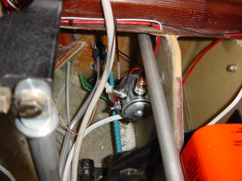
I first mounted the starter relay on the firewall and ran a #2 AWG (Wire Gauge) line from this point to the battery compartment in the nose. This line will serve as the main positive power line as the output from the two alternators will feed into the system from this point too - more on that later. Since this cable is too big for crimp terminals, I soldered the special lugs onto the end of the cable using a propane torch and attached it to the starter relay - this will be the 'hot' side. The other terminal (switched side) is attached to the starter via a #2 AWG cable in the same way. This was pretty easy..and was a good introduction to the processes that lay ahead. I also installed another 2AWG cable that runs down the other side of the fuselage that serves as the main grounding line - one end attaches to the negative battery terminal and the other is attached to the lower engine mount bolt. It then attaches to the engine via a flexible bonding strap providing a competed circuit back to the alternators - the great circle of 'electron' life is complete!
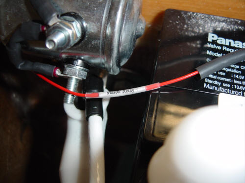
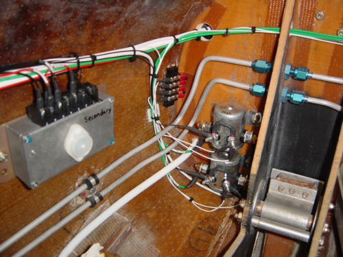
At the other end of the plane, I installed the battery, master relay, and battery bus fuse block. The battery bus fuse block will power and protect 'always live' circuits like the electronic ignition, cabin lights, and essential bus alternate feed, etc. The master relay is conencted to and controlled by the master switch and when energized, it will allow power to flow into the entire system. By the way, I have made the decision to label both ends of every wire that goes into this plane. I know it will add DAYS of time to the construction process, but since I plan to keep and maintain this aircraft for the next 20+ years...I feel it is time well invested.
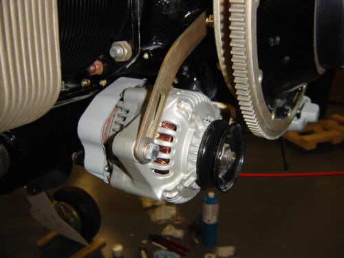
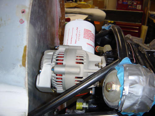
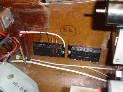
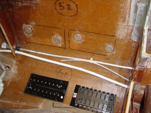
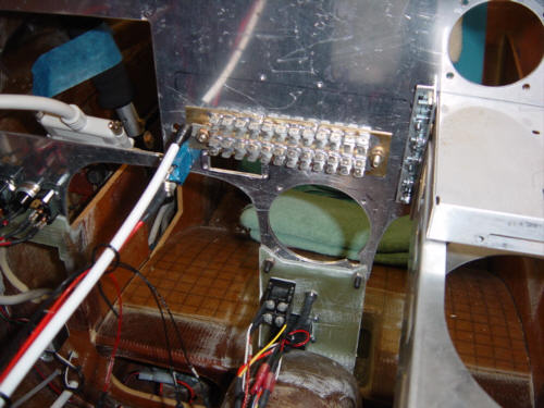
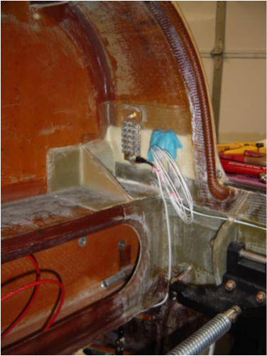
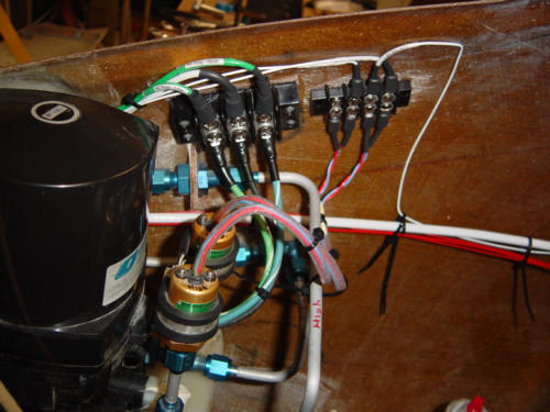
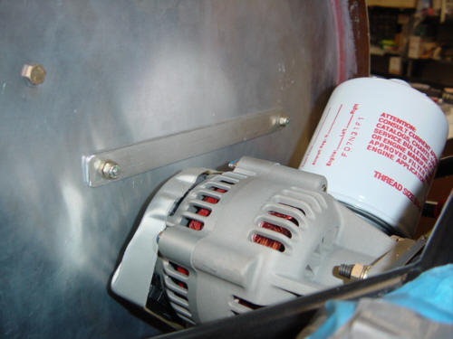
Next up, I installed the main and essential bus fuse blocks using a couple female EZ-point studs that are epoxied to the fuselage side wall. This makes them removable should I ever have to replace, or service them. You may have noticed the two 5A fuses and two red wires coming out of the primary bus block...those lead to the two B&C alternator and power regulators to keep those little electrons all marching to the same beat. These two units take care of regulating the primary alternator, and automatically engaging the secondary if the primary should ever fail. So, what's the gold thing with all the black wires, you ask? It's the forward ground block for all the equipment in the nose - nose gear, hyrdaulic pump, regulators, relays, etc. It's connected directly to the battery negative terminal by a 4AWG cable. There are two others like it - a 48-position block on the back of the instrument panel, and another 24-position block in the aft turtle deck. Terminating all the items to central ground blocks eliminates the possibility of ground loops and reduces induced noise in the system. On the plus side, I hooked up the main alternator to one end of the current limiter and the other to the starter relay positive side via a flexible battery cable from B&C.
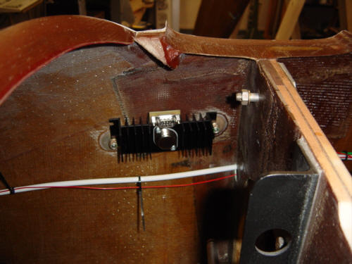
I also installed the dimmer module and heatsink in the forward nose section - basically to keep it out of the way of things. More on wiring the panel a little later in the panel section.
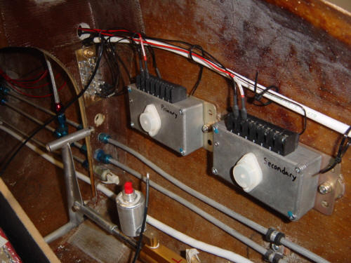
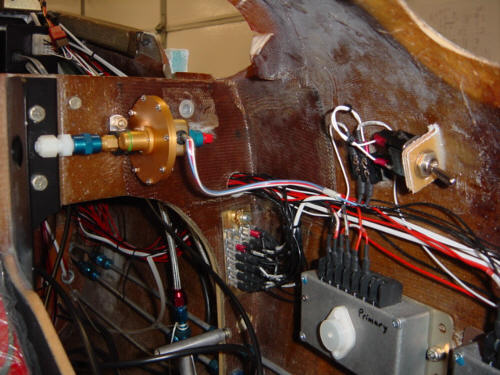
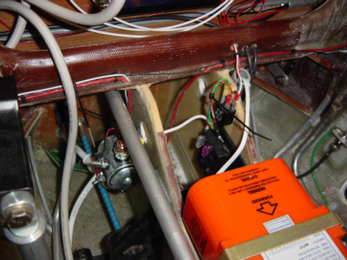
I now have the main gear hydraulic pump relays installed complete with pump status light and switch wiring. These realys are connected to the hydraulic pump and the pressure switches. Several weeks later in the process, I installed the air speed sensor and override switch. This pressure switch does not allow the main gear pump to be engaged unless the plane is moving 70+ mph. This is used to keep the main gear from accidentally being retracted on the ground. The override switch (on the right side of the pic) is used to by-pass the sensor only during ground maintenance and testing.
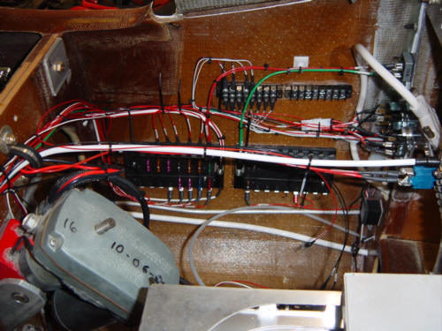
As of 11-20-03, I have all major power distribution items installed, hyd. pump & relays, nose gear actuator, and over 12 discrete electrical circuits (fuel pump, pitot heat, landing light, hobbs meter, pitch trim, etc.) compelted...and I have not even plugged in the first panel instrument or device. I am learning that wiring, when done correctly, takes a lot of time to complete! But, I sure like what I see so far!
By the way, the first of the 'smoke' tests are complete....and no smoke! (..uh, that IS a good thing!) I'll be working on items in this section all the time - so be sure to check the web cam too!
Update 12-15-03: I've completed the avionics wiring and installation. See the "Instrument Panel" section for details.
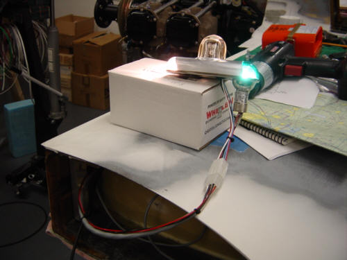
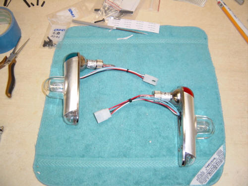
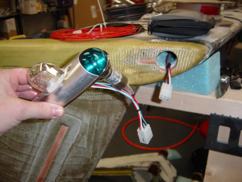
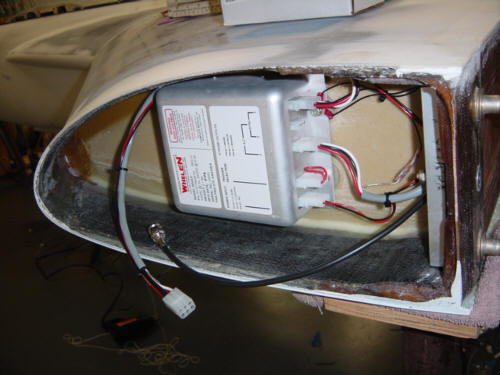
Update 12-26-03: I've begun the aft wiring now, and the first things to be hooked up were the Nav/Strobe lights - just in time for Christmas. I thought about rolling the plane out onto the driveway again, flipping on the strobes...and drowning out all the neighbor's Christmas lights. Instead, I just kept wiring. ;-) I'm using the traditional Whelen Nav/Position/Strobe Light assemblies that most canard aircraft are using these days - no surprise there. I also used the shielded wire that Whelen provides for installation, but I did install 6-pin connectors on the lights assemblies for easy removal and servicing. The assemblies just attach to hard points that are mounted in the wing tips and documented in the "Winglets Section". I installed the strobe unit in the left wing root/strake bay and ran the wires through the conduits in the main spar to the other side and aft grounding block. I'm using the "Comet" strobe style flasher (4 flashes in a row), with alternating sides. Man, those things are bright!!
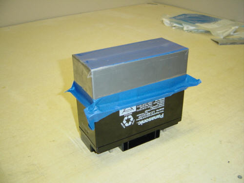
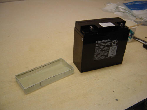
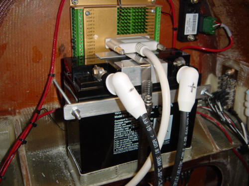
Update 1-10-04: Well...as things go with these airplanes...you sometimes just have to do some things over and over until you get it just-right. Thus is the case with my battery installation. First off, a little history - the Berkut was originally designed to use the Lycoming IO-360 engine. In the later years, Dave redesigned the plane to accommodate the larger 6-cylinder IO-540 engine and the plans and drawings were changed to reflect that. Well...for many reasons, I chose to stick with the 360 - forgot to consider that I need to reverse engineer the current plans accordingly. The airframe is the same for both models, but the placement of items in the nose and firewall are completely different - especially when it comes to weight and balance. Airplanes are just like "see-saws" in that respect and have to balance within certain limits to remain safe and fly efficiently. Now, while this plane could have flown safely with the battery in the nose, the "nose heavy" balance would have caused additional drag (slowing the plane down in cruise) and requiring higher approach speeds during landing. In addition, I could not use the 24lbs 28ah battery so I down sized to a 17ah (amp hour) battery - that is a more typical aircraft battery size anyway and less expensive. So, to the back of the bus with the 17ah battery and it's 14lbs of lead. You might think...no problem...just move it, but that is not all that has to happen. When you move the heart of the electrical system, then all of the power distribution system has to be changed as well. The challenge now is to move and re-mount the battery, the master relay, master switch wiring, all the main power and ground cables, the battery bus, essentials bus switch wiring, and the essentials bus alternate feed line. ...told you it was not that simple.
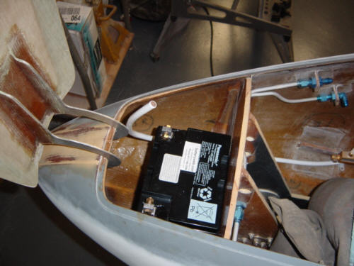
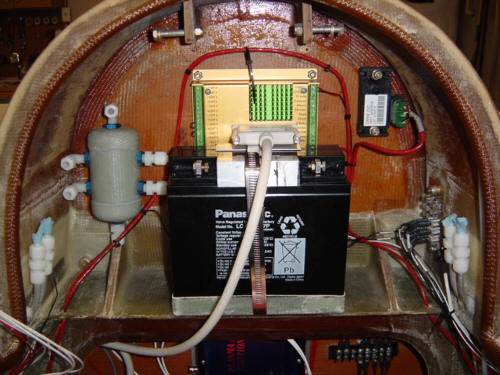
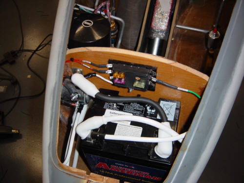
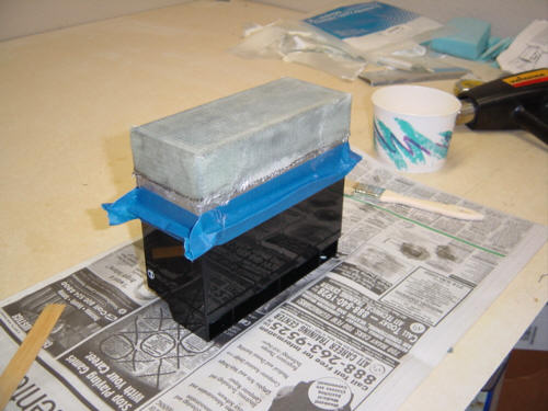
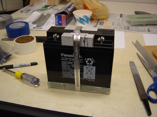
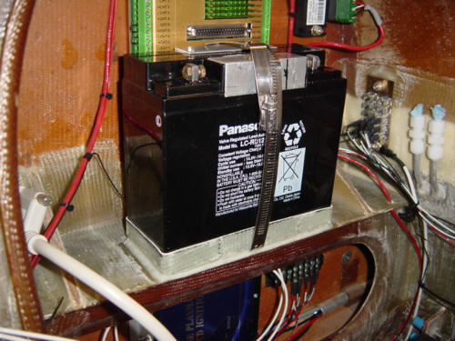
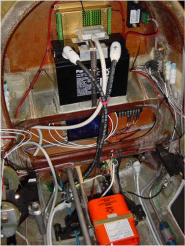
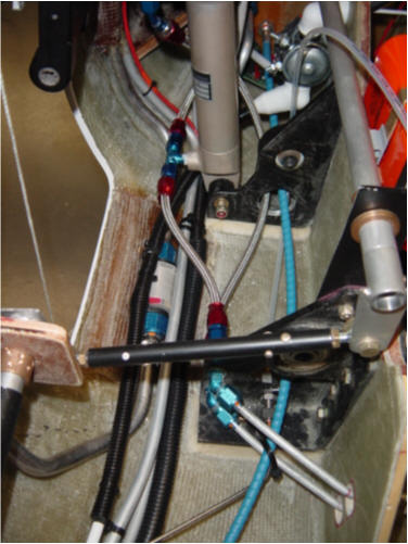
After looking at several spots to mount the battery, I chose the aft deck for easy battery access and simple "jumper cable" attachment if ever needed. So, the first step was to build a tray for the new battery - lets get moving. This was easy...I used the battery itself as a mold and wrapped release tape around the bottom and put a 2-ply BID lay-up down on top of it. After cure, I simply popped it off the battery and trimmed all the way around. I used a 5-7" diameter worm clamp for the vertical attachment to the tray along with a couple pieces of aluminum angle to keep from crushing the plastic battery case. Happy with this configuration, I mounted the battery tray to the top of the center spar with flox.
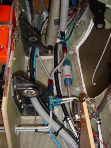
Next up - rewiring the power distribution system. Because I had the battery in the nose originally, I had to run thick & heavy #2-AWG cable on both sides of the fuselage fore and aft. That stuff was kinda expensive (15ft. x 2 @ $4/ft.) to be throwing on the floor, but now I only need much thinner #4-AWG cables since the battery is much closer to the engine starter (the highest electrical current load). This will also make the plane a few pounds lighter in the process...making it just that much more efficient - translation: "Faster"....so I bit the bullet. Now with the old cables removed and the smaller ones installed, I moved the master relay to the aft compartment and wired up a new, relay based essentials bus alternate feed system and new battery bus. To finish it off, I hooked up the new battery cables and tightened it all up. We have power...again!
Actually, these mods make for a lighter, safer, and more efficient electrical system than before. And, of course, I also have a more desirable CG (center of gravity) that will make the plane faster, and more maneuverable. I guess that makes all the extra work and expense worth while....but next time, I'll be more attentive to plans modifications for the 360 and try to get it right the first time. ;-)
Update 1-28-04: After pondering the new location of the battery for a bit, I thought about the crashworthiness of the current mount. I have no doubts about it during normal flight and even hard landings, but solid impact would be a little different. So, I added some aluminum bracing on the aft side of the firewall and tied it to another brace in front of the battery. With it all clamped into place, the battery is mounted very solidly! Now, during a sudden stop, the battery would have to rip the brace through the firewall to be slung forward...and if the impact is THAT hard, I think the battery is the least of my worries. ;-)
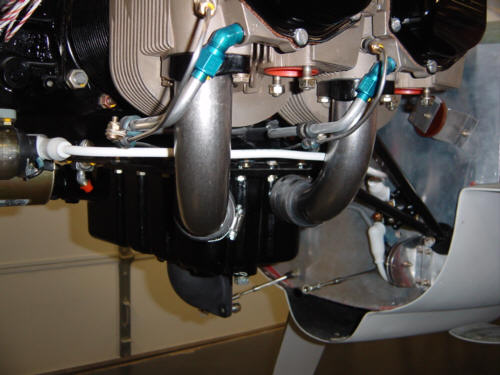
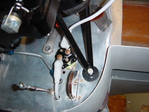
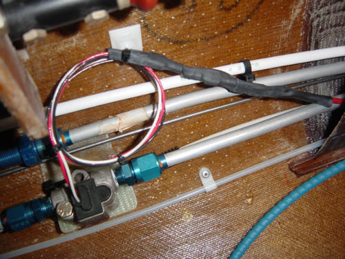
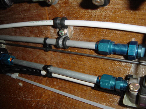
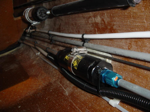
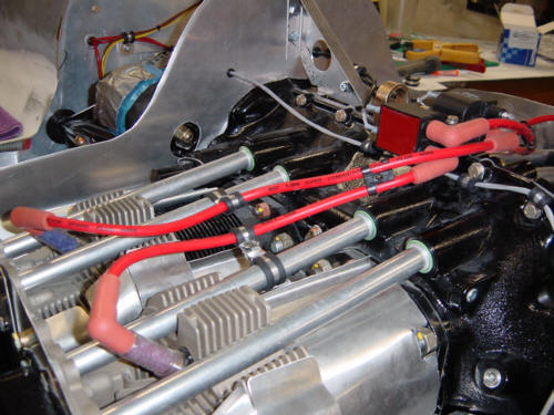
Update 3-14-04: Now that I am getting ready for engine start, I am going back and doing the final bracing, shielding and bundling of all the wires in the electrical system. I did much of this as I went along, but there are a few areas that needed special attention. First I went back and covered all the spade connectors on the ACS2002 engine monitor sensors with shrink wrap insulation for added protection. To keep the main positive power feed line isolated, I used two-way ZIP-ties and Adel clamps to stand-off and organize several of the lines at once. I added split wire loop material to any line that does or could come in contact to something metal or abrasive. This was especially important in the aft compartment where there are several moving parts and other hard and soft lines. In the engine compartment, I added several stand-offs for things like the ignition leads and other wires and hoses.
I hate to say it...but the electrical system in DONE! ...and ready for engine start and eventually....get this....FLIGHT!!!! Who would-a thunk-it !?!
 Back to the Proto-page