
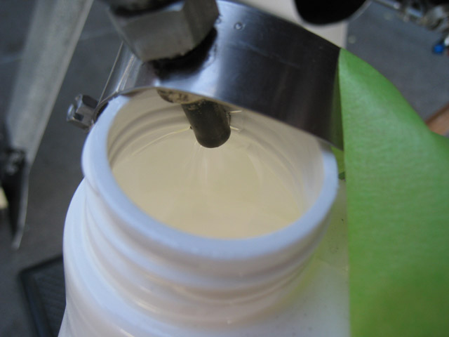
Ever since I starting flying formation and air racing, I've been thinking about putting a smoke system in the Berkut. The only problem is that all the off-the-shelf systems out there don't really fit in the airplane. I knew I was going to have to make my own. I searched the web and found surprisingly little about building a good smoke system. There were a few gems of knowledge and technology I came across and one is the key to this project's success. I came across some instructions written by Marvin Holmsley that simply describes the components and specifics of a successful smoke system. As he indicates, the most important part of the system is the injector. Marvin developed (and markets) a great injector that is easy to install and creates a fan-pattern spray. More information and ordering details available at his website: www.smoke-system-helper.com So, I bought a set and I'm glad I did - they REALLY work!
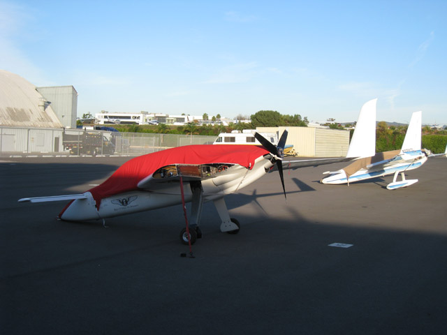
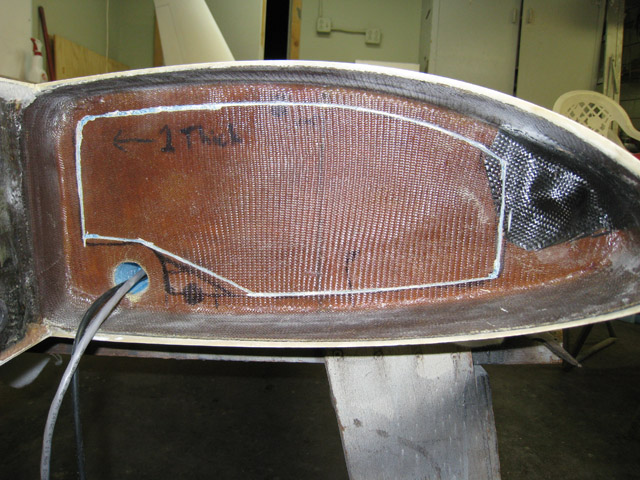
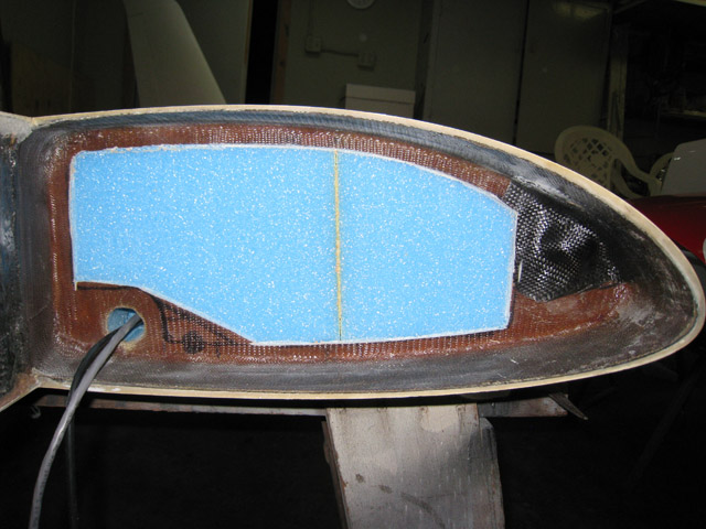
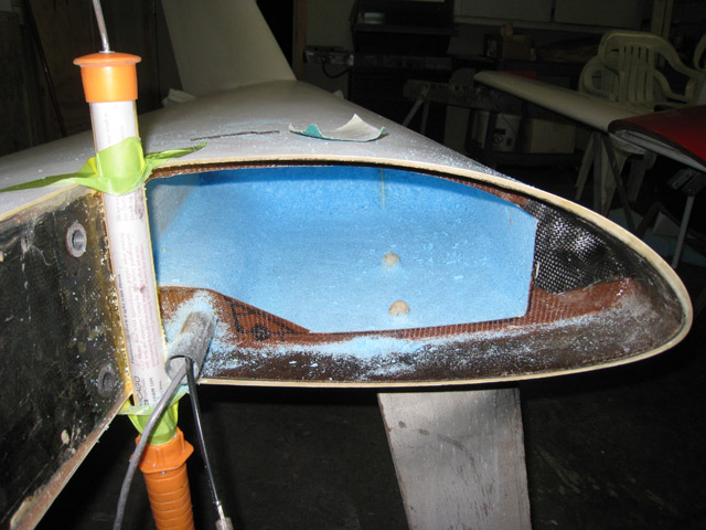
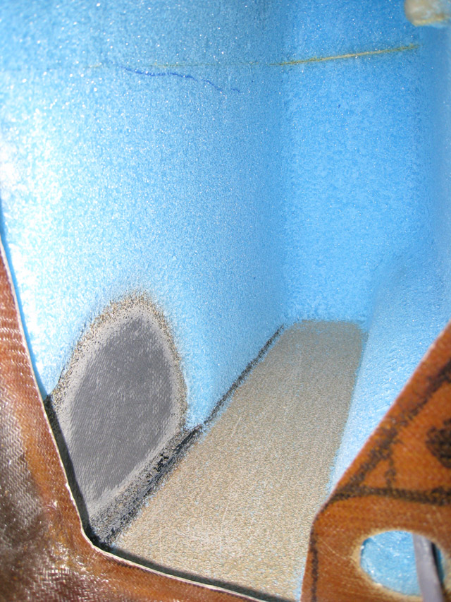
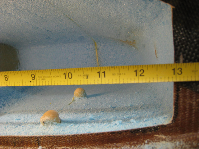
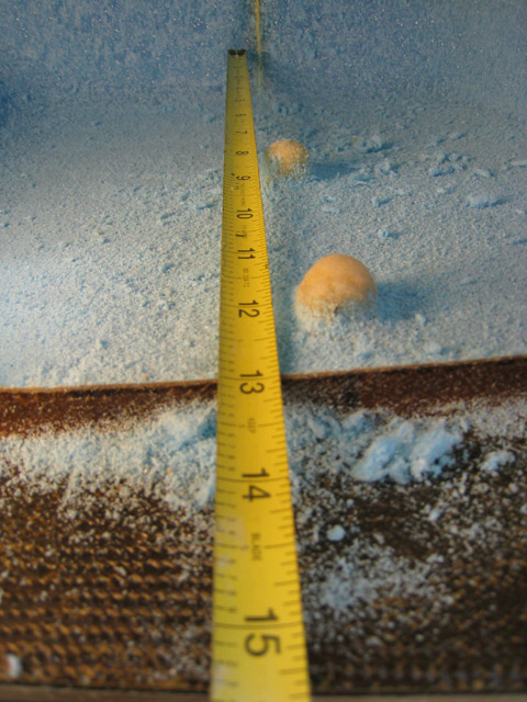
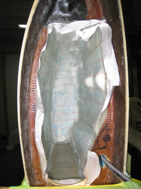
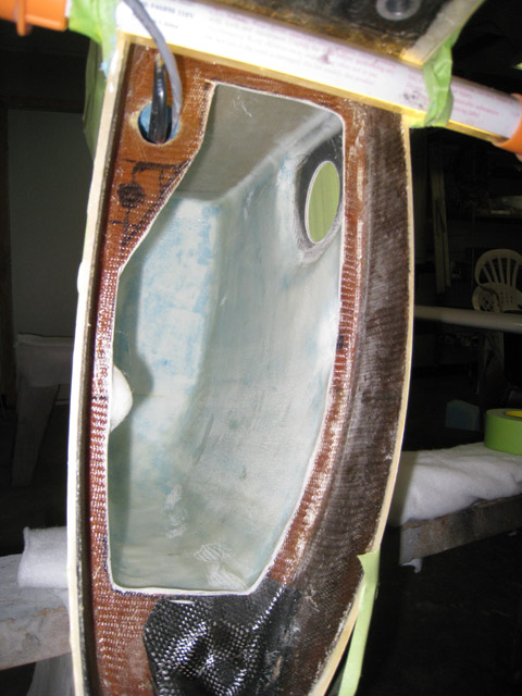
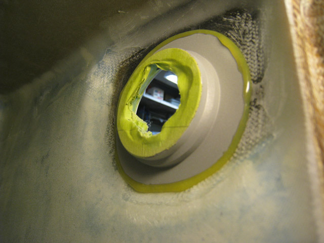
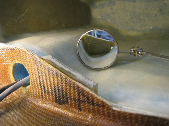
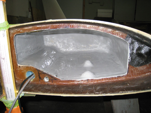
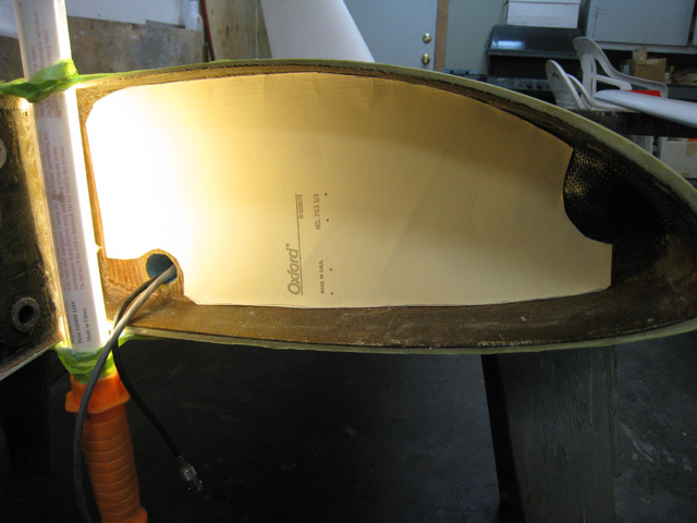
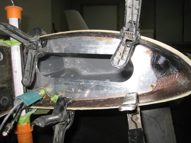
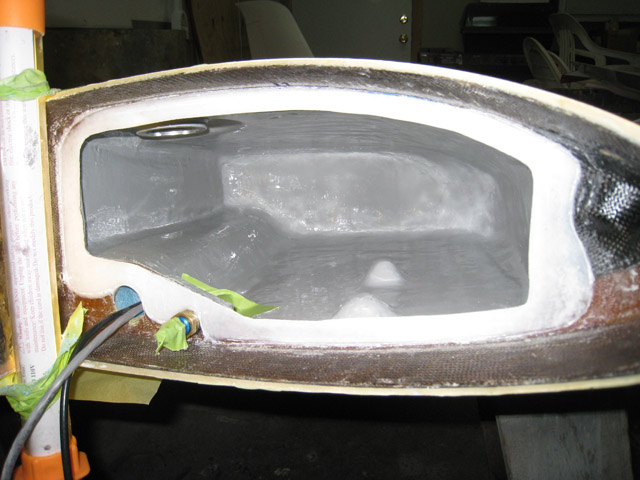
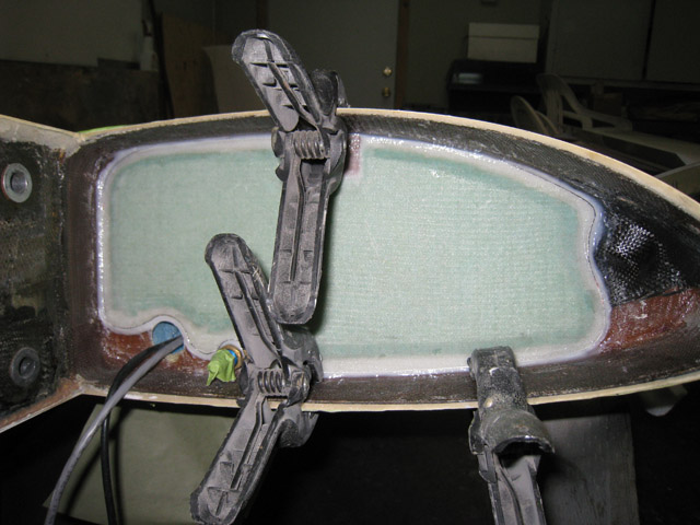
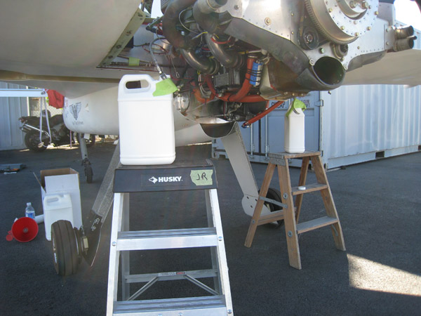
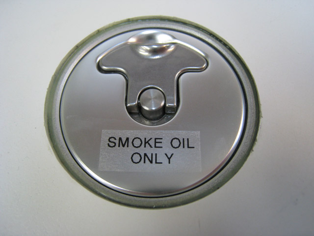
So, while 'Thirteen' is out in Santa Monica, I had some down time while doing some maintenance mods. I pulled the left wing off and got started! The first thing I needed to build was an oil tank. I didn't want to use a temporary tank in the passenger compartment or take up precious baggage space in the strakes...so, I decided that I would make a tank in the leading edge D-section of the wing. The Berkut molded wings have a 8-gallon aux fuel tank in this position, so I figured I could easily handle a smaller 4-gallon tank built into the foam core wing and the CG calculations agreed. I planned out the basic dimensions on the D-rib and made the cut...no turning back now. I left a space for the lower pickup hardpoint and cut around the wire conduit...I didn't want to have to integrate a tube and worry about it leaking. After removing the bulkhead cut-out, I starting cutting and sanding out the foam in the D-section to create a tank cavity leaving about 3/8" of foam around the entire parimeter. (the bumps on the bottom are flox covered hard points that were installed for the baggage pods) Once the foam was shapped, I removed all the foam and sanded the skin area where the cap will be installed. So this point, I took some quick measurments in order to estimate how much the tank would hold - seriously, I DIDN'T PLAN THIS...it came out to be thirteen by thirteen inches. Seriously! I knew, right there...I was done digging. I won't bore you with the details...but some paper templates, slurry, micro, flox, 2-ply BID glass, and peel-ply later I had the tank all skinned and let it cure. After cure, I cut the filler cap hole and bonded the retaining ring in place. I cut a piece of G-10 and bonded it in place and tapped it for a finger screen. I had shaped a trough in the bottom of the tank so that the pickup would be at the lowest point in the tank. Just to be sure I didn't have any leaks, I applied a coat of Novalac 9700 tank sealant and installed the pickup screen. The tank was done, but it still won't hold anything until I replace the D-section rib.
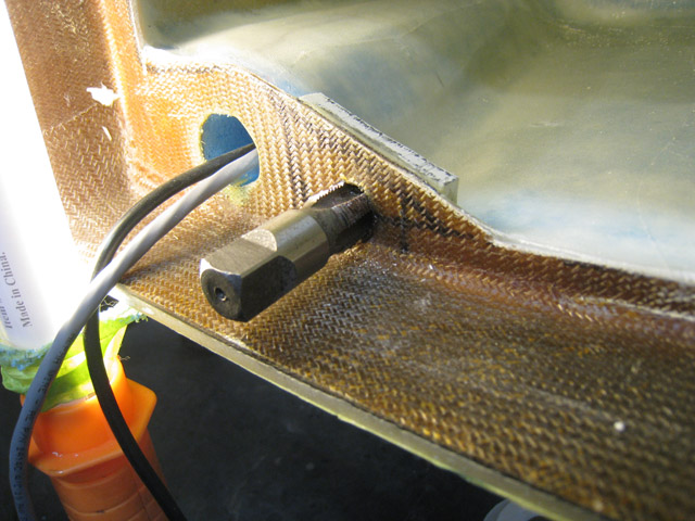
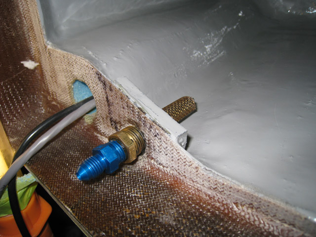
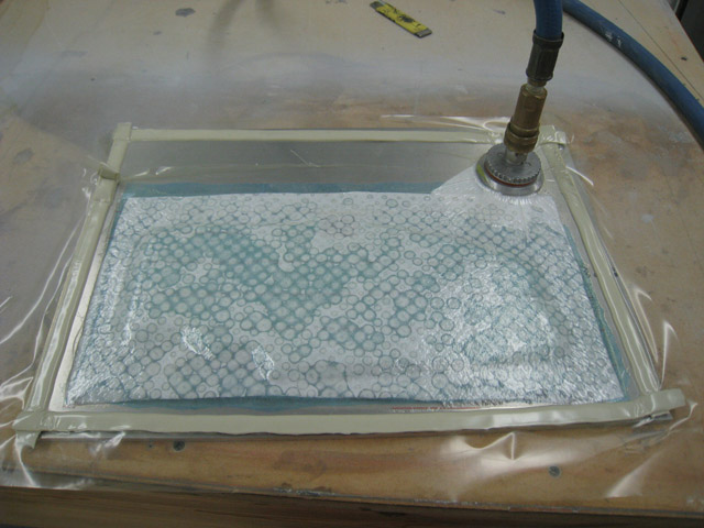
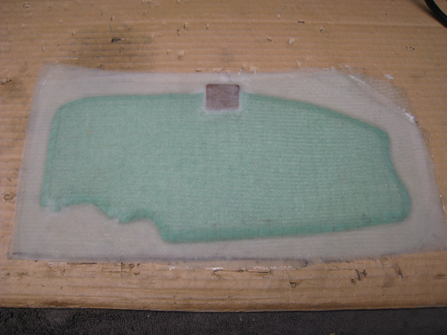
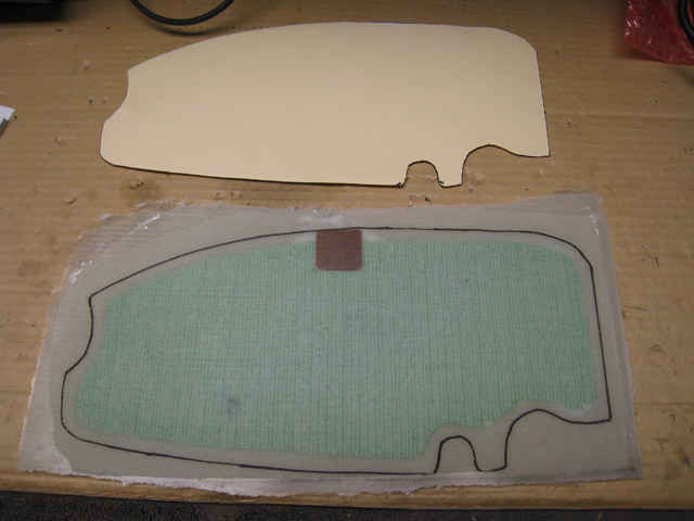
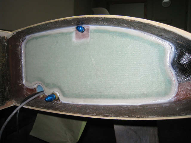
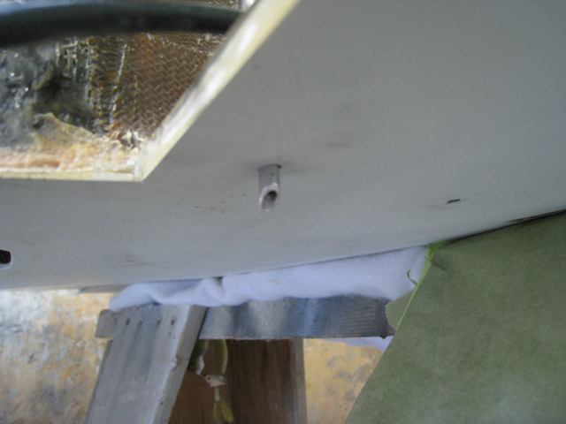
Replacing the D-rib was really easy. I just made a paper template and used it to shape some .25-inch PVC foam. A little 2-ply BID and a vacuum bag later I had a raw bulkhead. Once it was trimmed to fit, it could be bonded back onto the remaining D-rib flange. Unfortunately, the original D-rib was layed over hand-carved foam and was not all in a flat plane. So I made an aluminum plate and used it as a form to create a smooth flox surface around the D-rib. I used 3M DP460 structural adhesive to bond the new bulkhead onto the D-rib. I had previously drilled and tapped the upper vent fitting hardpoint, so all I had to do now was to install the AN fitting, run a vent line out under the wing, make a pickup hose and the tank is complete.
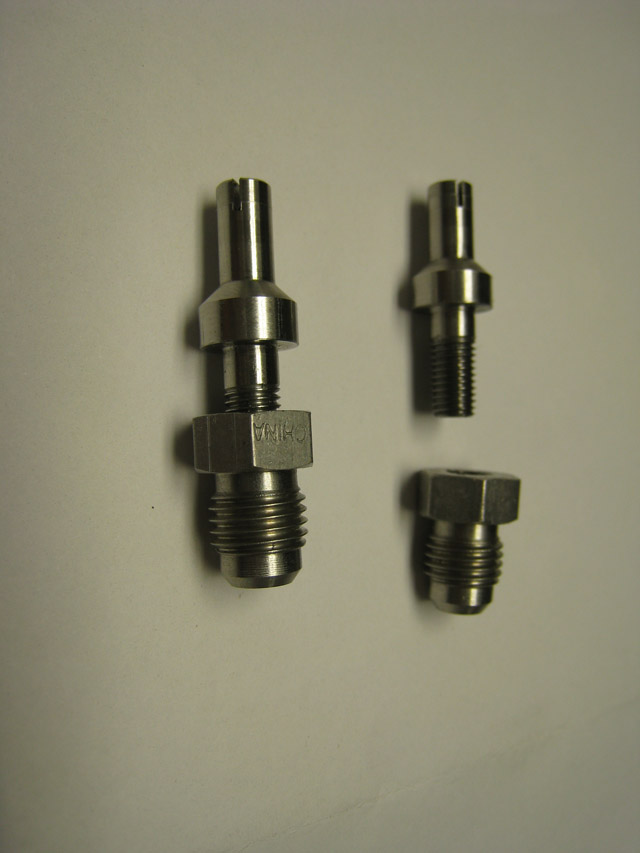
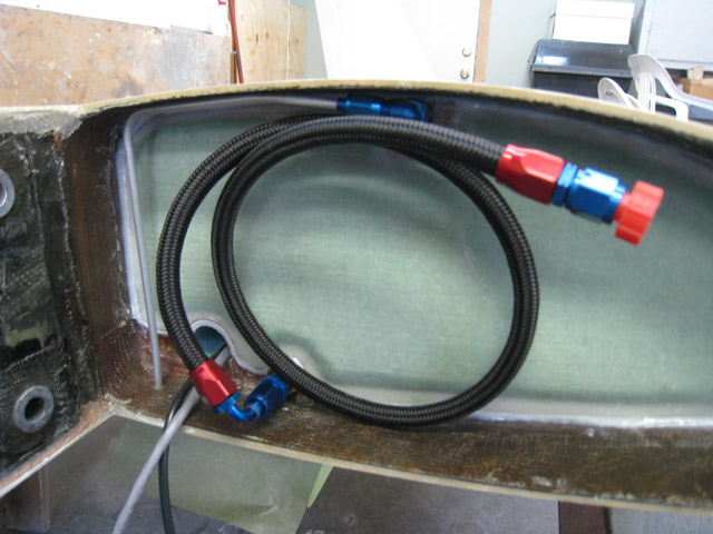
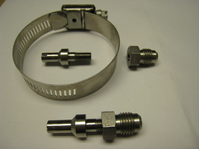
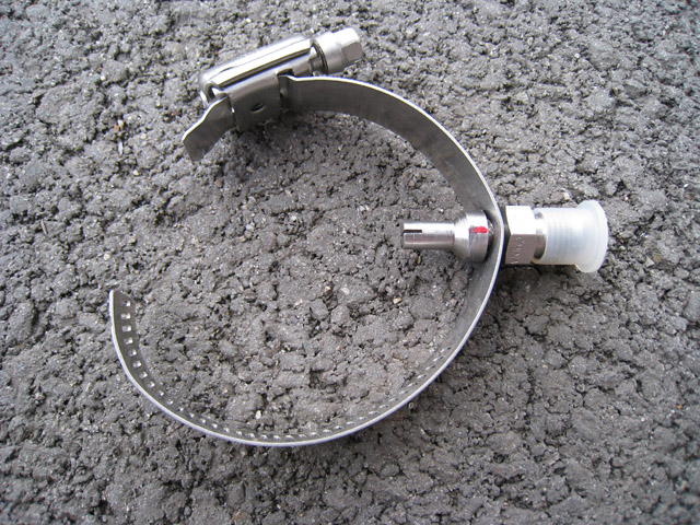
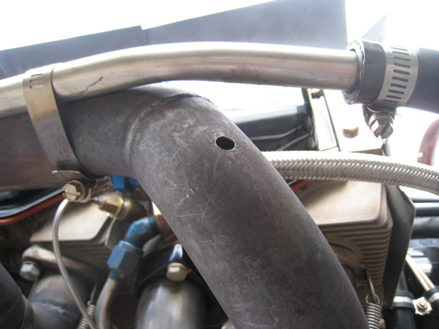
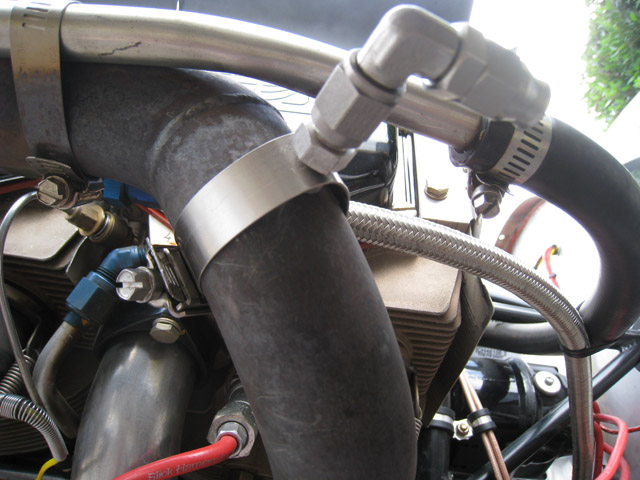
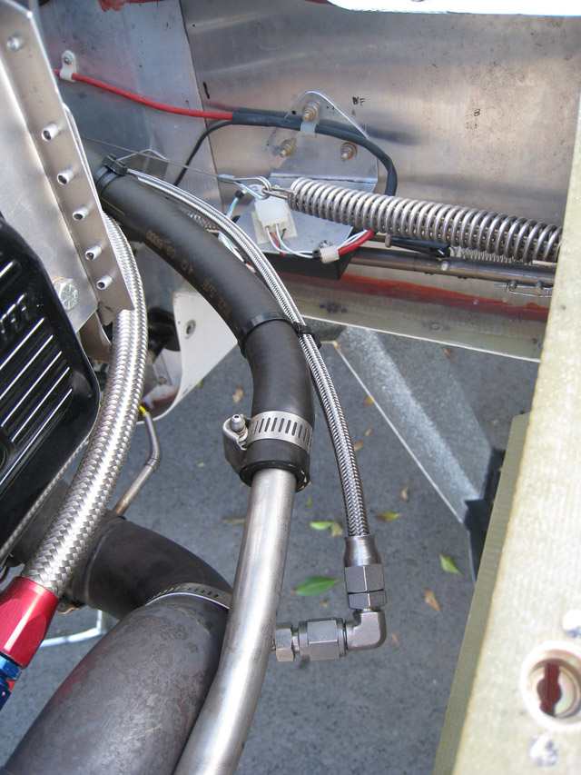
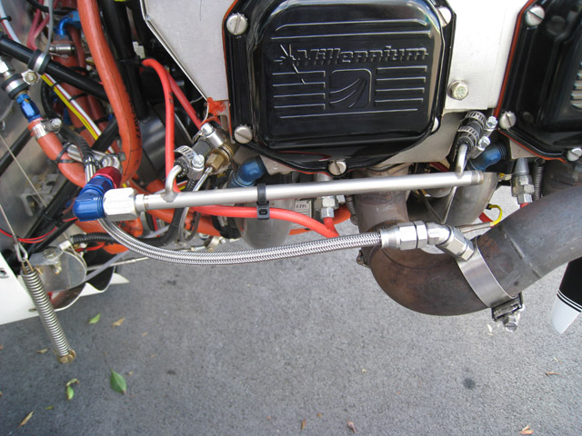
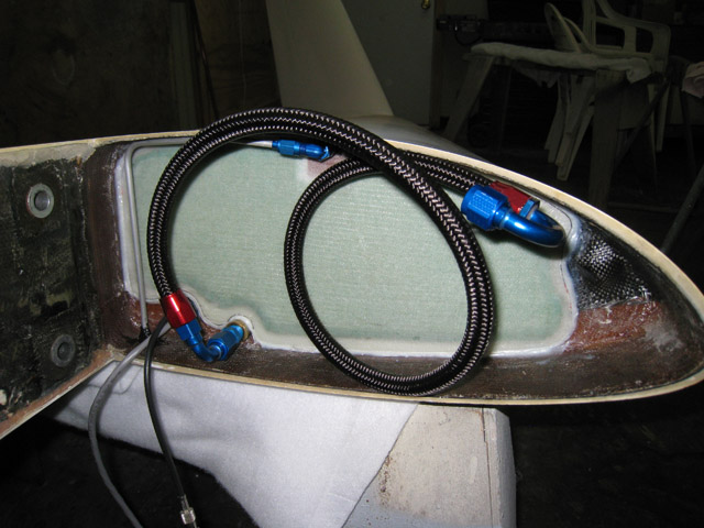
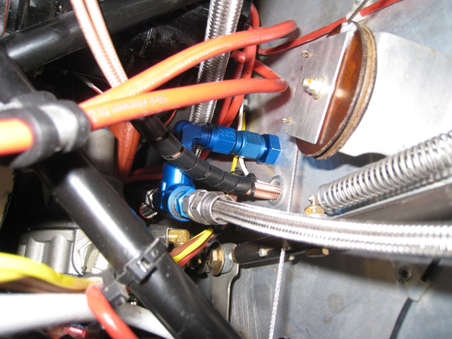
I mentioned the injectors earlier, so lets start there. The injectors break down into two parts so that they capture a stainless steel worm clamp. They install simply into a .25-inch hole drilled into the exhaust pipe and clamp onjust like a EGT probe. The slit that creates the fan spray is oriented perpendicular to the exhaust flow. Stainless steel fittings and .25-inch braided Teflon hose was used to connect the injectors to the Tee fitting at the firewall. The two injectors are installed on opposing cylinders, in my case they are installed on cylinders 3 & 4. (firing order 1,3,2,4)
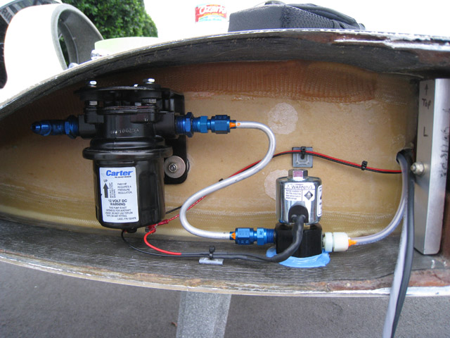
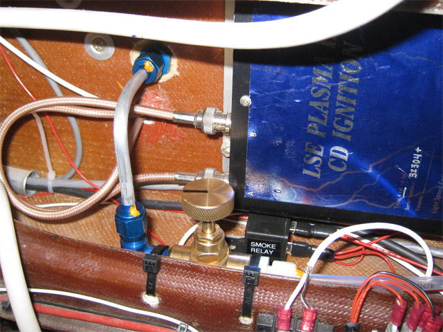
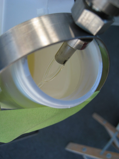
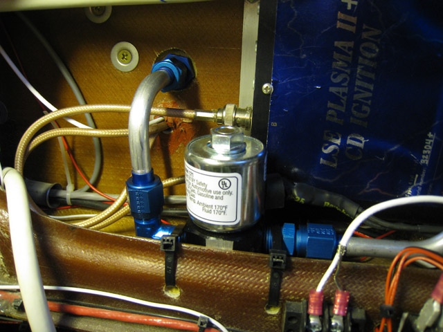
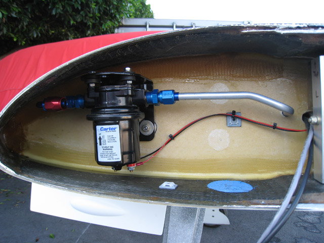
The tank was alot of work, but came out perfectly...the injectors are great, but the rest of the system took some trial and error, lots of testing, and two versions to get right. Oh well...the adventure made the victory even sweeter! After searching the web, I selected the Carter 4601HP fuel pump because of it's small size, 100GPH and 18psi pressure ratings. The control solenoid is a high-flow Diesel fuel cut-off valve Model 121 made by Advanced Fuel Components. I installed the pump and solenoid in the wing/strake intersection cavity that used to house the strobe power supply. (I recently upgraded to AreoLED units and revoved the strobe box) I ran a .25-inch Nyla-seal tube through the spar conduit to a needle valve where the flow can be regulated. Then used aluminum hard line to a bulkhead fitting to penetrate the firewall. When it was all plumbed, I filled up the tank and ran some flow tests. I was VERY disappointed to discover that I was only getting .2GPM through the system. That's WAY too low to make effective smoke...you need close to .75GPM and that was what I was originally shooting for. Here's a video of the first test (4.5mb). There was definately a restriction in the system that was limiting the flow rate and dropping the pressure so much that the injectors were barely working. UGH!! So, I spent all day taking parts out of the system and re-testing to find out what the restriction was...it turns out, the -4 line itself was too limiting. In retrospect, it makes since...
Obviously, I needed to re-work the entire system. I decided that istead of going to a different pump to increase the pressure, I would just re-plumb to all with -6 lines. It wasn't too difficult...just new fittings and hoses. (sigh) I made a new pickup hose, deleted the needle valve, and moved the solenoid to the center spar section so it will be closer to the firewall Tee. I connected it to the pump with a hard line through main spar. I had to increase the firewall tee size too...but I left both injector lines at -4. I re-ran the flow test and BINGO, I got a little over .75GPM out of the system. The injectors finally had enough pressure to create a nice fan spray. Sweet! And, as you can see from the video...it's making PLENTY of smoke...this is going to be FUN!!
There are not a lot of canards out there with this cap on them. But I bet that the ones that do are more fun. ;-)
Back to the Proto-page