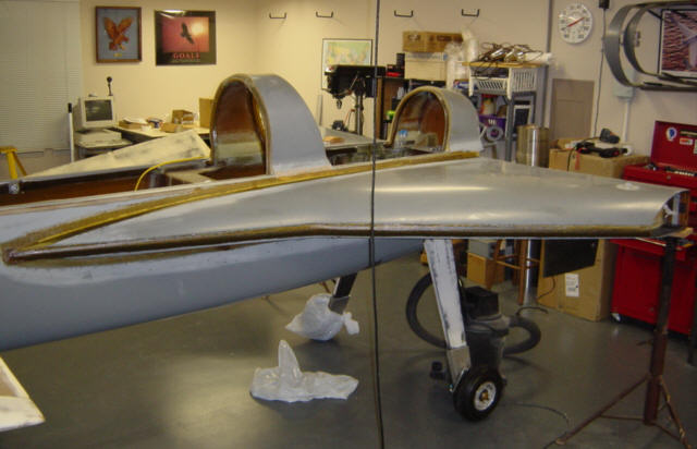
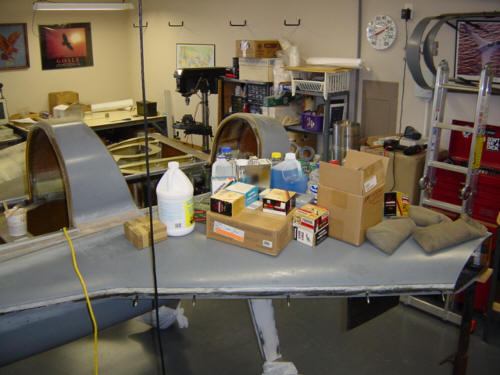
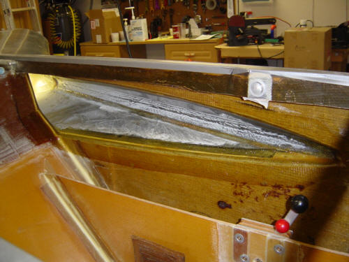
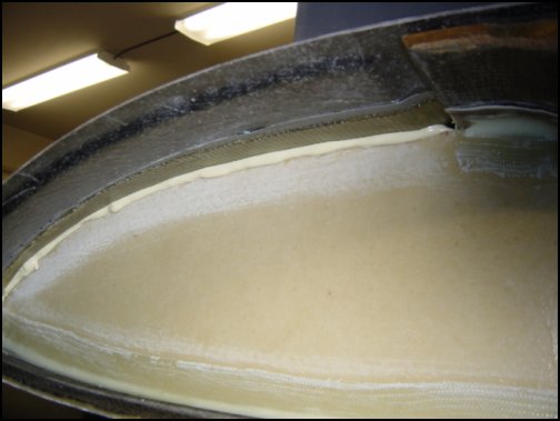
The big day is here! It's time to close the strakes. The first step is a doozie - sand everything! Both the upper strake and the lower strake and ribs have to be sanded to assure a good bond for the sealant and final assembly. I used JeffCo 9700 epoxy tank sealant (the grey colored material) to coat the interior surface of the upper and lower strakes. This will make sure that any pin-holes in the carbon will be sealed and not leak. Come to find out - it's the same stuff that I used to coat the workshop floor. Go figure! Then I used a pastry bag to apply a bead of wet flox to the T-tapes and the forward intersection of the strakes. Once the flox is in place the upper strake is carefully placed back on top and 100+ pounds of weight is used to press the top strake into position and 'squeeze' the flox into place. Let that cure overnight and I'm happy to report that all went well and the strake is now very well pookied into place.
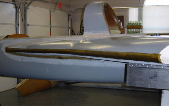
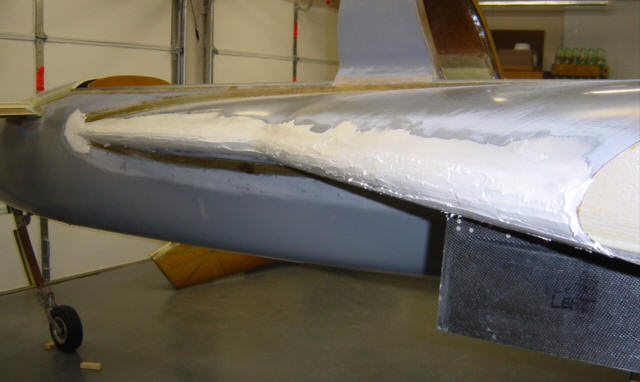
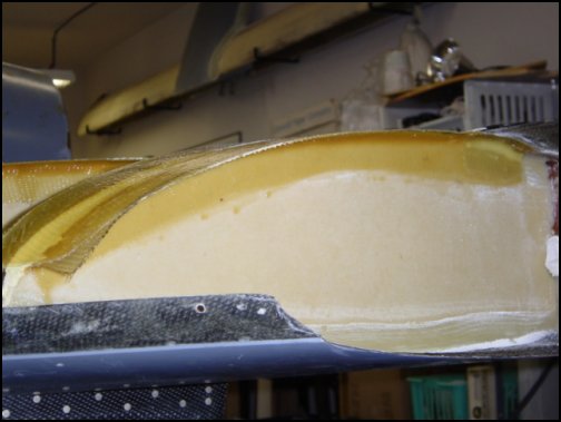
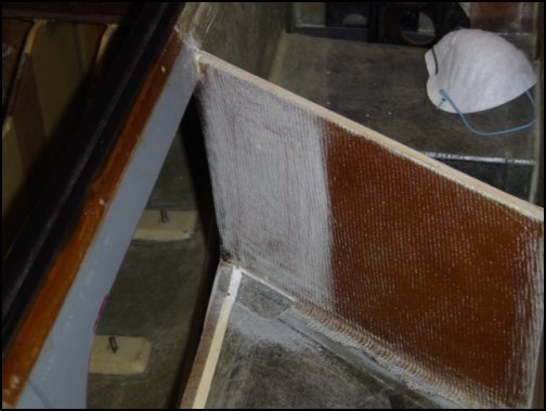
Once the main cure-cycle is complete, it's time to move on to the finish work. First, there is a 4-ply BID tape added to the leading edge of the strake. This fits into a molded joggle and completed the seal between the two strake halves. Then, smaller 2-ply tapes are added to strake/fuselage intersection's top and bottom surfaces - something has to hold it onto the side of the plane, ya know. One thing here that made me very nervous - cutting and tapering the hole in the fuselage for the pilot's baggage opening. But, all went well and looks great after the tapes and some flox were added. Soon after the front tape semi-cured, dry micro filler was applied to fair-in the leading edge and make a smooth transition. Since the tape was only semi-cured, I was able to get a chemical bond between the micro and the tape - this will provide a stronger leading edge.
The right strake was much easier to do, since I now know what I'm doing BEFORE I do it! That perspective is valid to only those people that have 'been there, done that'. Nothing special to report on this strake, although it seemed to take much more weight to get the proper oozing but turned out great.
More work to do here with filling and sanding. I'll post some of that here next.
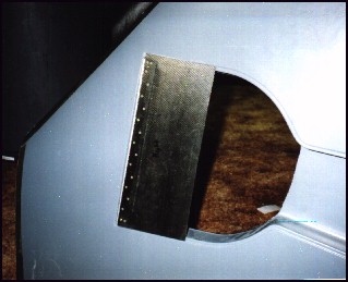
The first step to installing the strakes is to fit the main gear doors. The doors come pre-molded and shaped perfectly (to within .020 inch). These are the newer gear doors that do not have the blister for the Cleveland brakes - I'm using the Matco brakes. Installation is simple, sand to fit, install the hinge on the door and match drill into the strake hardpoint. VIOLA! Installae est!
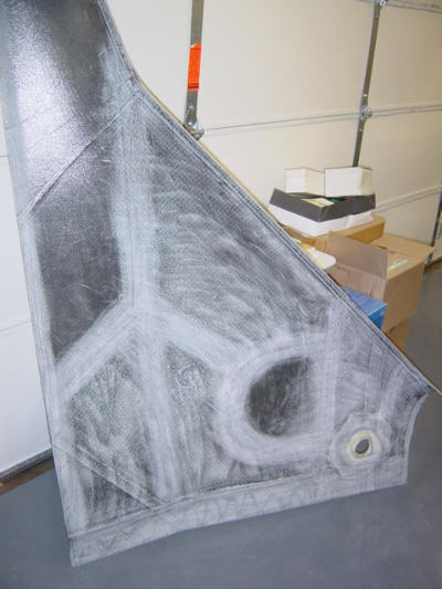
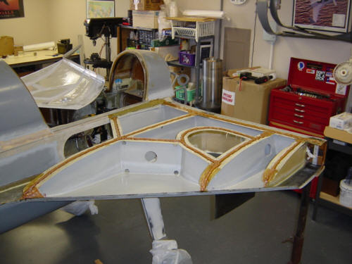
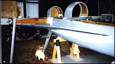
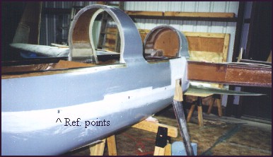
Then, the strake bonding area must be sanded and preped before positioning the lower strakes. The rear of the strake is clamped to the bottom of the spar and the strake is moved into correct position. The molded carbon strake is VERY stiff and holds its shape while it is positioned on the fuselage. The upper mold line is used as a water-mark and is easily leveled. The builder simply matches the outer end to the wing root and the front tip is measured down from the longeron level, check level at the center and pookie it into place. At this point, it is important that both sides are symmetrical so the reference marks are transferred to the opposite side. These marks are then used to position the second strake and then minor corrections are made to assure both sides are the same - then the second lower strake is installed. Additional checks are made with the upper halves in place, as referenced to the longerons.
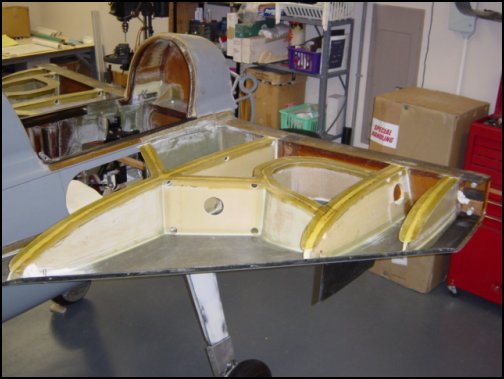
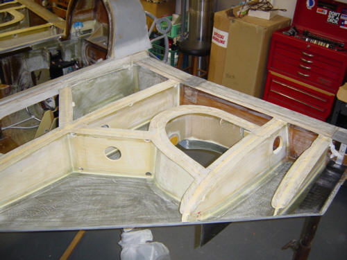
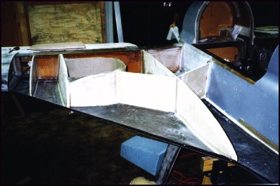
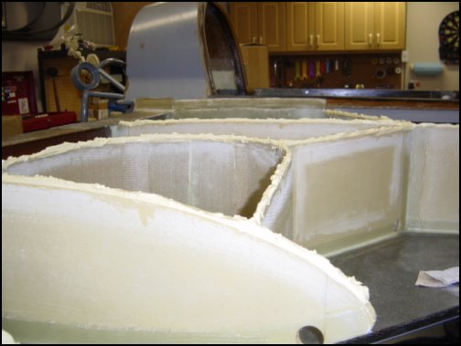
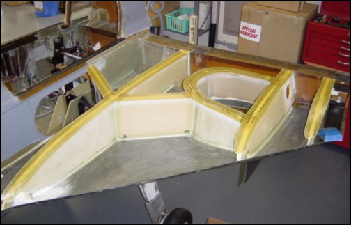
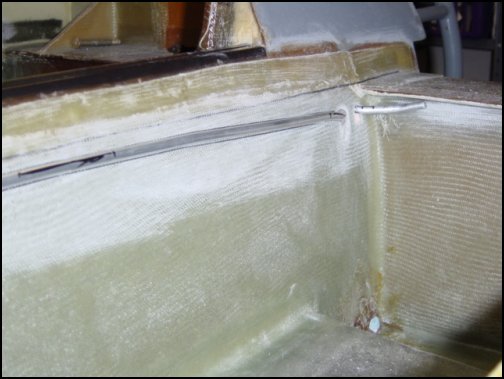
The strake ribs are cut out of bulk stock that comes with each rib clearly marked. Just cut them out, trim to fit, match the upper surfaces to the upper strake and bond in place with 2-ply BID tapes. The curved gear-well is custom made by the builder using flex-foam and 2-ply BID as seen in the above pic. The inner plys overlap the strake gear-well flange making a perfect seal. Here is what it looks like when the ribs are installed.
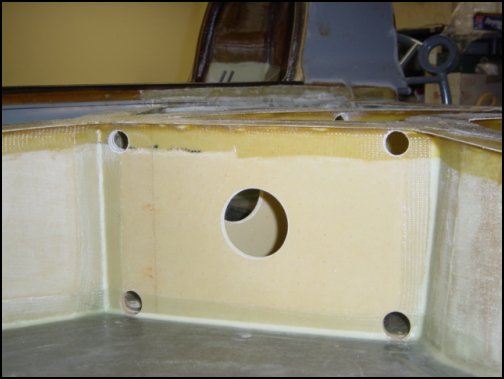
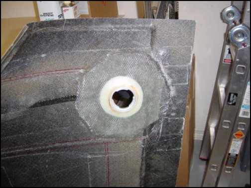
A 7-ply BID re-enforcing lay-up is added to the inner-tank across the fuselage, spar and baggage bulkhead. This will provide added strength for the gear assembly and a solid mounting area for the fuel pick-ups that will be added later. Rear baggage area access holes are cut out of the fuselage and preped for the fuel gauges to be installed.
Several other small projects take place before this step, but this is as good a place to put the T-Tape information as any - so, here it goes. The purpose of the T-tapes is to provide additional bonding/sealing area for the top strake. The original Long-EZ plans called for only flox corners, but since Berkut is capable of higher G-loads - the strakes need to be more rigid.
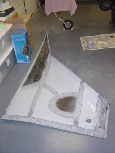
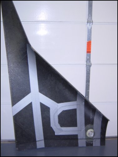
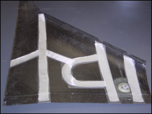
The process starts out by marking the locations of the strake ribs onto the upper strake so that duct tape can be attached as a mold release. Then, 2-ply BID tapes are wet-out on top of the duct tape and let to semi-cure for 30-mins. This forms the upper part of the 'T' and uses the upper strake as the mold. 1/2-inch of dry micro placed on the tops of all the ribs in preparation of bonding the new 'T' tapes. The strake with now semi-cured tapes is placed on top of the Micro and weights are added to the section over the spar to press it all down. As you can see here, the extra squeezed-out Micro is cleaned up where accessible, flox fillets are applied and 2-ply BID 'L' shaped tapes are attached connecting the rib to the upper part of the 'T'. After allowed to cure over-night, the tapes are trimmed to size and all the previously inaccessible ribs get flox fillets and 1-Ply BID 'L' tapes.
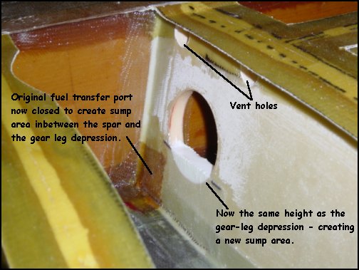
After those tapes cure, everything is trimmed and edges smoothed. Vent holes are drilled in all the top corner intersections to allow proper venting of all compartments. Additional large fuel filler holes are drilled to allow a faster filling of all the compartments when filling the tanks.
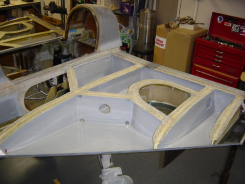
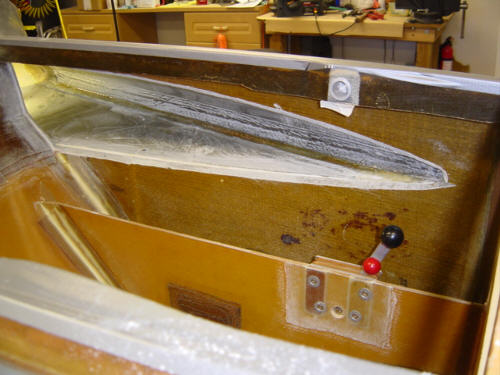
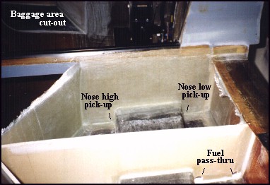
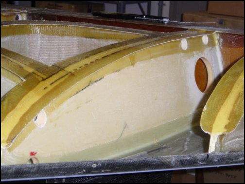
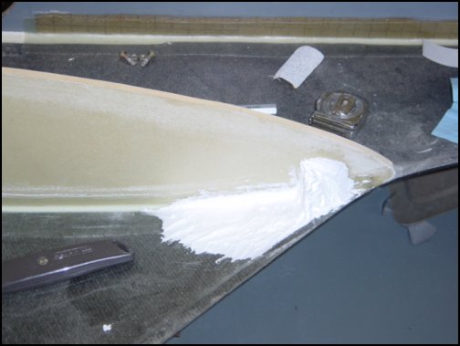
Since I originally installed my strake ribs years ago, I needed to make a few modifications to create the New Fuel Sump area. As you can see in this photo, I blocked off the original fuel transfer hole, and raised the lowest point on the fuel filler hole. My original hole was lower than the top surface of the gear leg depression, so my sump area would not have been able to properly hold the fuel. Now, as far as structure goes, the strakes are complete and ready for sealing and close-out - coming soon.
Fuel guages, vent lines, vent manafold, and vent ports:
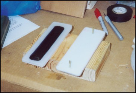
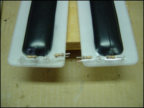
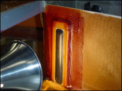
I am using the standard fuel gauges that have been used on countless Long-EZ's. They are made by Vance Atkinson of Ft. Worth, TX and he can be reached at: nostromo56@tx.rr.com if you want some too. The sight gauges come from Vance in two pieces, a white back plate and a clear bubble front window both made from P.E.T.G. fuel resistant plastic. The two parts are bonded together using West epoxy and small brass tubes are added to the backplate. The center bubble is covered with several layers of black electrical tape to protect it through the rest of the building process. Once dry, I added two 2-Candella (bright red) LEDs and appropriate resistors in each gauge. These LEDs will provide plenty of light to see the fuel level at night - without degrading my night vision.
Next, the rear baggage area bulkhead is sanded and prepared. The top layer of skin and foam from the lower strake is also removed in front of the gauge to make room for the LEDs. Finally, the whole assembly is floxed into place and 2-ply of wet BID is applied to all sides of the gauge. The area where the LEDs are is filled with micro and covered with a ply of BID. Viola! Sight gauges. The tape will remain on the bubbles to protect them until it is time to paint the interior.
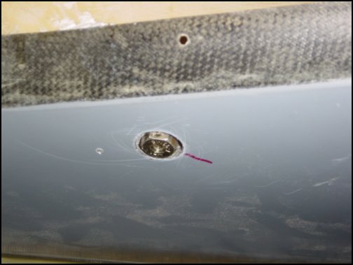
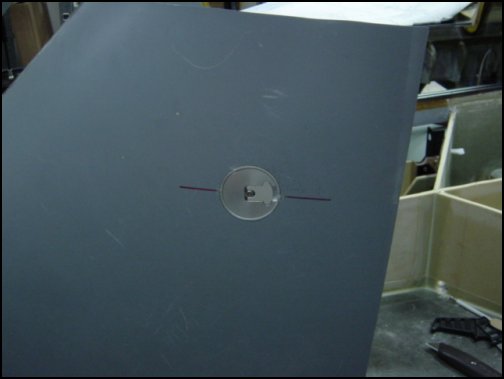
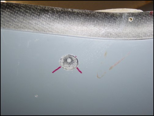
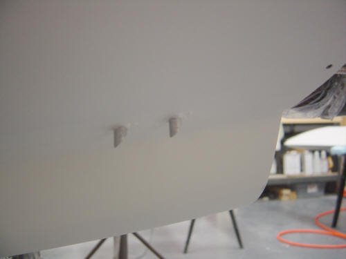
These recessed fuel drains are located on the lower front of each strake. The idea is that they will be the lowest, most forward point in the tanks when the plane is in the 'parked' position. This way any water that may be in the tanks can be removed before flight.
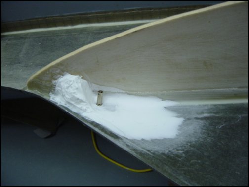
The first step is to drill an oversized hole into the strake and leave the lower skin intact. A 1/4-inch thick aluminum hard point is burried under flox and micro, and a small ramp of micro is installed just in front of the hardpoint.
Finally, the micro is smoothed out into a ramp and a hold is drilled, tapped and the valve is installed.
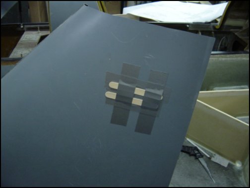
Not much to describe on these fuel caps. They are specifically designed for composite aircraft and look great! They were very easy to install. You first start by drilling a large hole in the strake where the cap will go. Then cover the hole with duct tape and tongue depressors. This allows the cap's collar, a ring of flox, and 3-ply BID to be installed while keeping the top side flush with the top skin. VOLA! You have fuel caps.
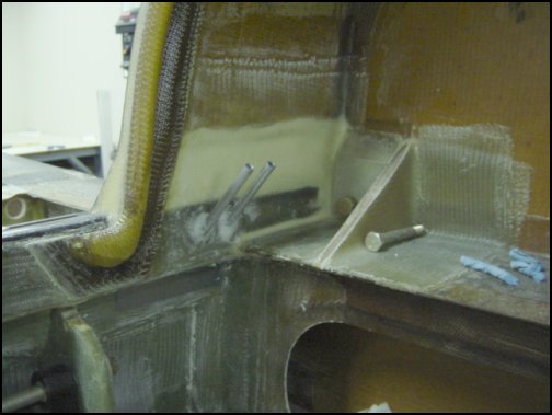
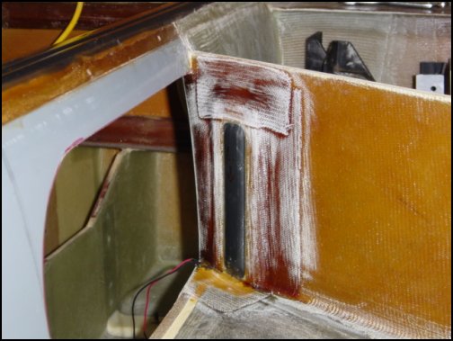
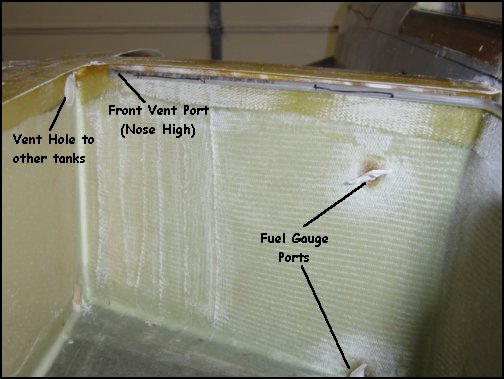
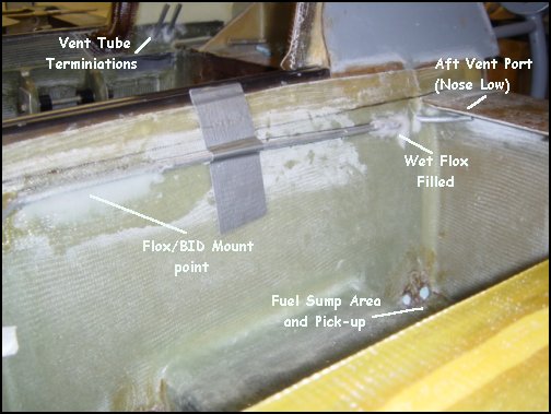
Since the strakes contain the fuel tank compartments, it is important to vent those tanks so that fuel can flow properly. First note from the T-tape section above, that there were vent ports frilled into all the upper intersections of the tanks. This is to eliminate the possibility of creating a vacuum inside any one compartment. The procedure is very simple. First, I drilled diagonal holes from inside the rear deck down into the inboard strake tank. Then 1/4-inch aluminum tube is installed to provide two vent ports in the highest tank positions - aft for nose-low, forward for nose-high attitudes. The forward vent tube terminates just prior to the vent hole to the forward compartments. The tubes are then floxed into position. Wet flox is used to assure a good bond to the aluminum tube and tank seal. The internal port terminations shown above will connected to the vent manifold at a later date.
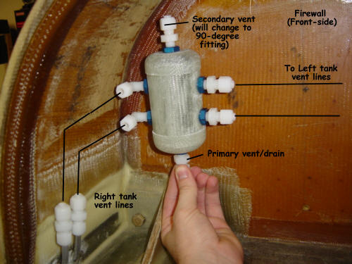
The vent manifold is a Berkut exclusive as far as I know. The purpose is simple - the fuel tank vents in the strakes sometime burp gasoline out the vents...this can't be helped. On many planes, these vents would simply terminate as a hole on the outside at the top of the firewall/cowl intersection. This works but it causes 'burped' fuel to run back over the cowl and stain it. This device eliminates any holes on the top of the airplane and prevents any unsightly dribbles. It also vents both tanks to a common pressure so that both tanks flow evenly regardless of the amount of fuel in each tank. Kewl, huh!
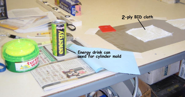
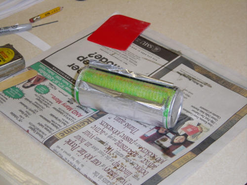
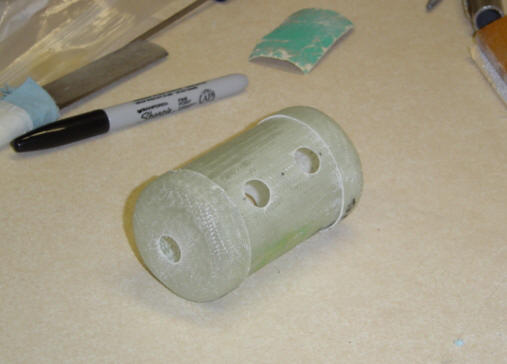
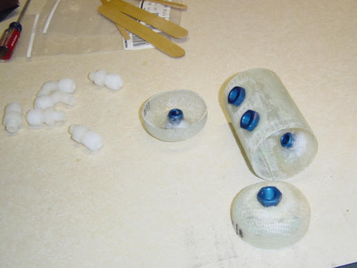
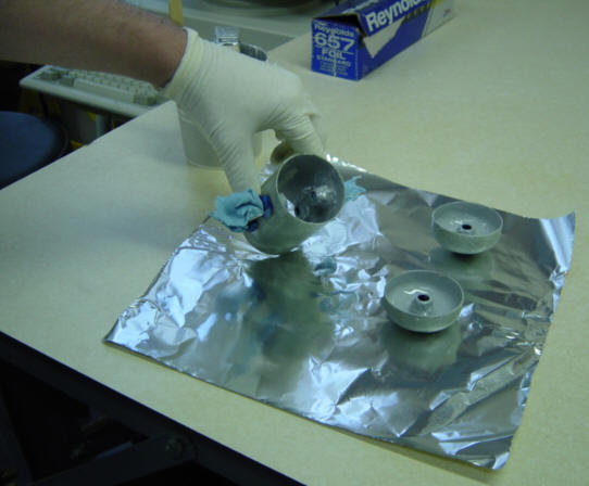
Making it was a bit of a challenge, but was fun and easy. I first started with the raw materials needed: an energy drink can with a diameter of 2.25 inches, some 2-ply BID, wax, and some foil for the transfer. First, put some wax on the aluminum can and then transfer the 2-ply BID foil and wrap it around the can. Peel the foil away and let cure. After cure, remove the aluminum can from the glass tube and discard what's left of it. This now forms the main body of the manifold. The end caps are created by first shaping some blue foam end caps then wrapping them in duct tape as a mold release and making a 2-ply BID layup over them. Let cure and repeat for the other end. NOTE: when I cut the main tube down, I used the left-over part as a mold for the 2nd cap. After the caps are cured and trimmed, I drilled the holes for the aluminum pipe reducer inserts. I had to use AN912 aluminum inserts because the epoxy does not stick to the nylon fittings. It also allows me to change the type of fittings used depending on my final placement and piping. Next, the aluminum fittings are cleaned, prepped and bonded into place with wet flox. After cure, the nylon fittings can be easily installed into the aluminum fittings. Presto! A vent manifold is born!
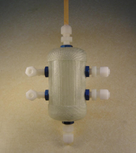
Final fitting included coating the interior with JeffCo sealant and bonding the two caps on at the same time. Nylo-seal tubing will be used to connect the vent lines to the manifold and the manifold to the vent/drain exit ports on the bottom of the plane. For those interested, I think this method can be used on all 'EZ' type models. Overall, I am very pleased with how this part turned out. It is lighter than an all metal version, works equally well, and was cheaper to make! Can't get much better than that...except for one thing: no special tools are required - especially those icky metal working tools! ;-)
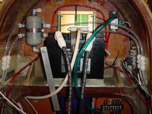
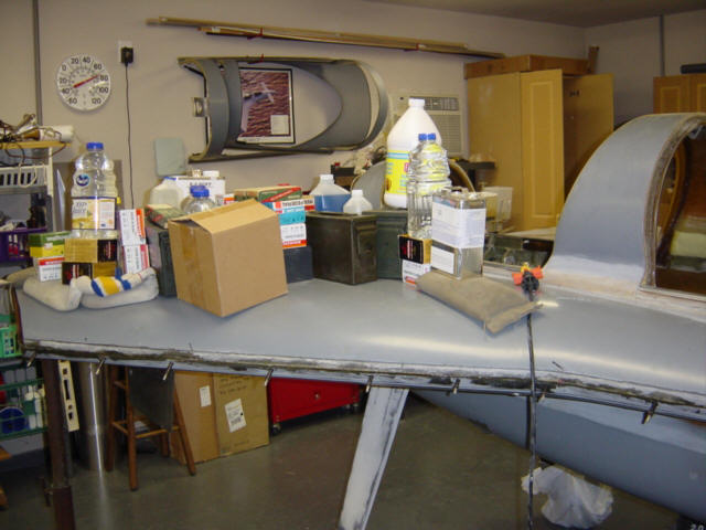
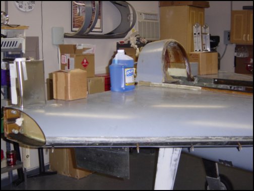
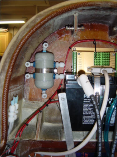
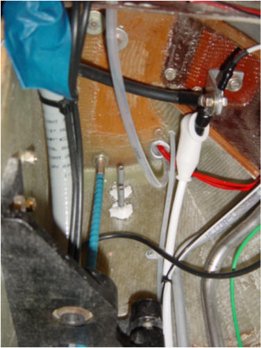
UPDATE 2-1-04: As you can see in the picture above, the aft deck has become much more "busy"...and one of those things is the mounted vent manifold. It's attached to the firewall with a worm clamp that is bonded in place with a 2-ply BID tape and some flox filler. You can also see the Nyla-Seal lines that run from the vent lines in the strakes to the sides of the manifold. The upper and lower ports are vented directly to the outside. So, I also had to install two short 1/4" aluminum tubes in the bottom of the aft fuselage. These external vent ports not only allow redundant vent sources, but they also direct any expanding fuel out onto the ground without getting any on the paint. Nice!
 Back to the Proto-page