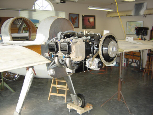
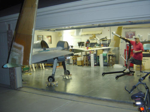
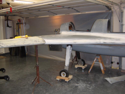
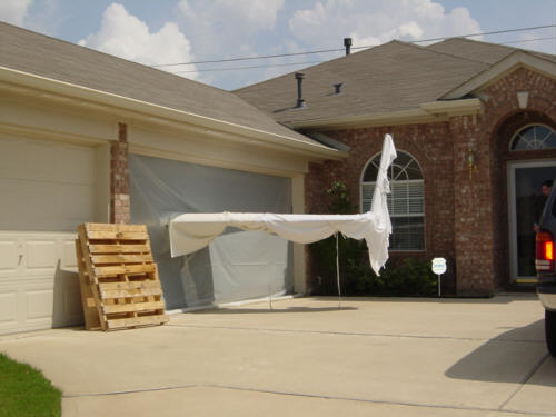
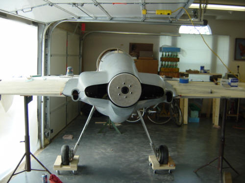
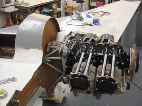
The engine installation took place over the 4th of July holiday. The objective was to install and align the engine so that the upper and lower cowls could be fitted at the same time. This operation also required that BOTH wings be installed at the same time. This presented one of the biggest problems with the garage workshop. One of the wings had to stick out of the garage for a couple of days. We sealed the door opening back up with plastic sheet to keep the A/C in and it worked out pretty well. However, we did get several curious looks from the neighbors during the next few days. You might also note the main-gear casters we made to help move the plane around in all 360-degrees (another $20 invention worth noting).
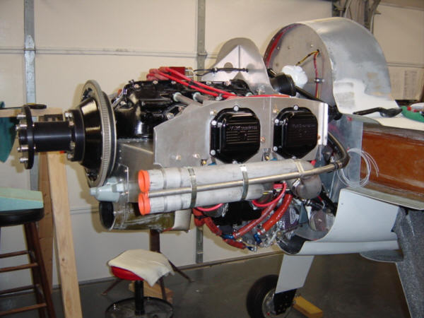
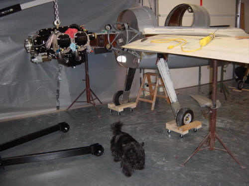
Now that the shop was prepped and the plane was positioned, it was 'all hands (and paws) on deck' to hang the engine. The critical part of this operation was to verify that the engine's crankshaft is perfectly on the centerline of the aircraft....and it was! It fit perfectly - without the need far shims or adjustment...another victory!
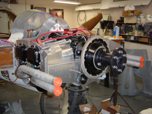
A trial fit of the cowls, with the prop extension and spinner bulkhead in place, verified that everything was right on the mark.
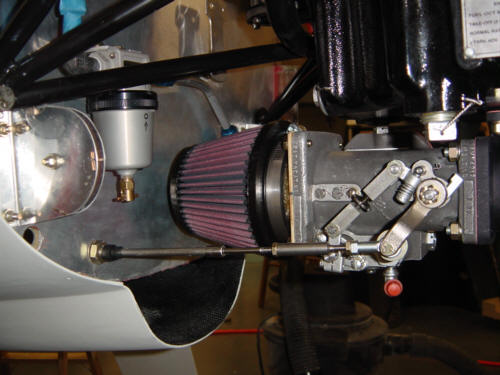
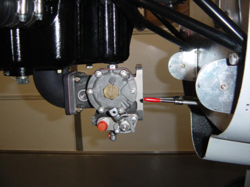
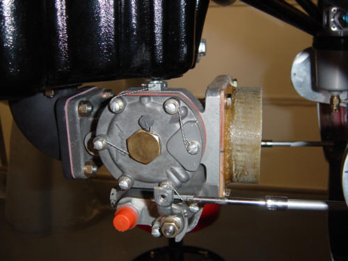
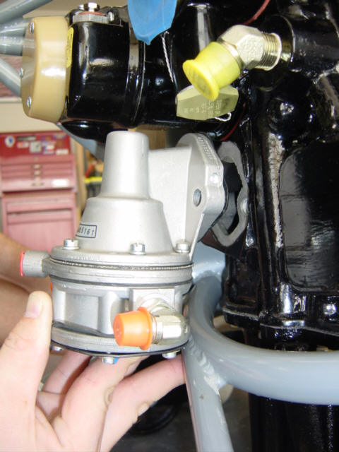
This section comes after a 2 month pause as I finished the bottom of the fuselage. Now that it's done, I have flipped the plane back over and have started the engine hook-up. The first item on the list is the fuel injection servo - as you can not get far without any fuel. I choose to use the Bendix servo unit over the Airflow Performance unit mainly due to a simpler installation. As you can see in the picture, the unit can be easily rotated and installed facing the aft (aircraft-forward) face of the engine. The AFP unit is bulkier and does not fit under the oil sump without extensions, wedges and a secondary mounting structure...too much work for the fractional increase in HP in my opinion.
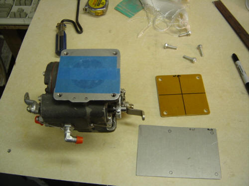
Having a little background in racing cars, I really wanted to use a K&N conical air filter and that meant I would have to do some custom adapter work - No problem! I started by cutting a piece of 1/8-inch thick phenolic to fit the intake side of the servo, match-drilled the holes and marked the center of the plate. This forms the mounting flange that bolts to the server body itself. Next, I logged onto the K&N web site and did the math for the IO-360 @ 3000 Max RPM. The calculations led me to the correct size filter in the shape I desired - the RU-2990 with a 3.5-inch mounting flange. OK...now I need a 3.5-inch diameter collar for my phenolic plate so the filter can be attached with a worm clamp. Looking around and measuring EVERYTHING in the shop - I have NOTHING that is a suitable mold!! Grrrr!
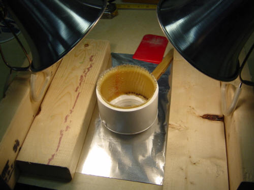
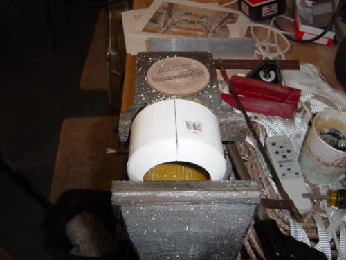
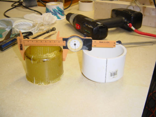
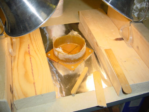
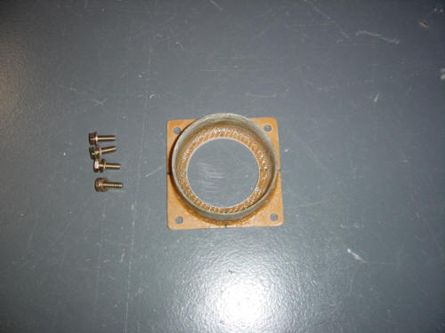
During a quick trip to Agent Orange (Home Depot - it relieves me of my green everytime I walk in the door), I found the perfect mold - a 4-inch PVC pipe end cap. The I.D. of this thing is perfectly 3.5-inches and only $2 green dollars later it was mine. So, I waxed it up, cut a hole in the bottom for access, and layed up 3-ply BID inside the cap. Once cured, I carefully cut a slit in the PVC cap and used a screw driver to pry the sides apart so I could separate the newly formed collar. B-U-T-FULL! It came out a perfect 3.5-inches in diameter. Mating these two items was also very easy - I attached the collar to the phenolic with flox and 2-ply BID. After cutting a large opening in the plate for the intake runner, I made a successful trial-fit on the engine. All is good to go!
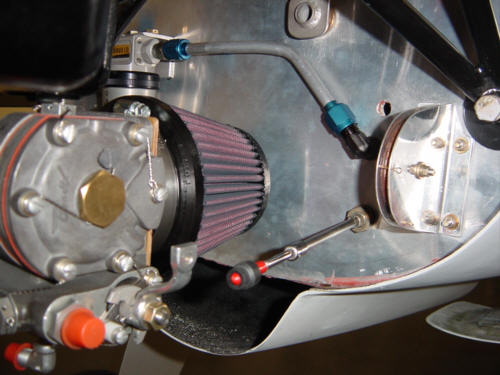
I choose the conical filter mainly for the smaller foot-print on the firewall but it is also a simpler installation and lighter than the aluminum plate/oval filter/spring mount that was originally called out. As you can see here, I have alot more clearance and room on the lower firewall...mission accomplished!
UPDATE 3-1-04: Moving ever closer to engine start! I spent this last weekend doing what I hope to be the LAST engine pull and install. I still had many odds and ends to complete and finalize and it all necessitated the removal of the engine to do it....(sigh). So, off it came!
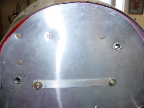
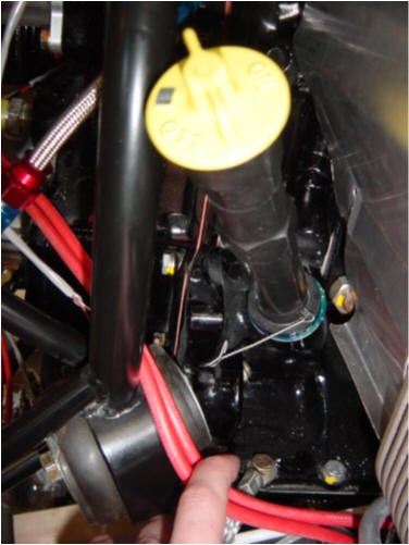
The first task at hand was to drill out and install the last of the firewall conduits. Now that all the equipment is mounted in the turtle-deck, I was able to locate the best place for some holes, drill them 5/8" and install the flared aluminum tube. My wonderful wife Sandy was kind enough to lend a hand holding the bucking block inside the fuselage as I pounded out the flare on the other side. What a trooper!!!! I could not have done it without her. As both of us had out hands full, there are no pictures of the install - but here are the finished upper and middle conduits. They look darn good too! Then I turned my attention to all those engine accessories that needed to be torqued down and safe-tied. First up was the oil dipstick. Wow! That was easy...NEXT! I also tied down the vernitherm and oil temp probe. Ok...getting a little harder...then...the fuel pump! The one part that just doesn�t have a good way to safe-tie to anything. After a quick consult of the books...here's how to do it. Ok, that was not so bad after all. Now, if I just had the prop... 8-p
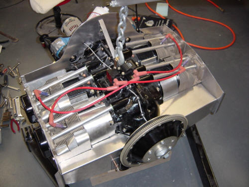
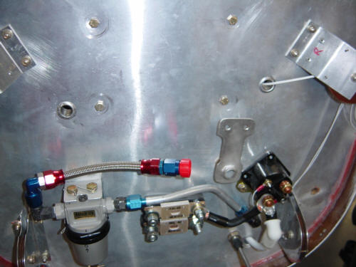
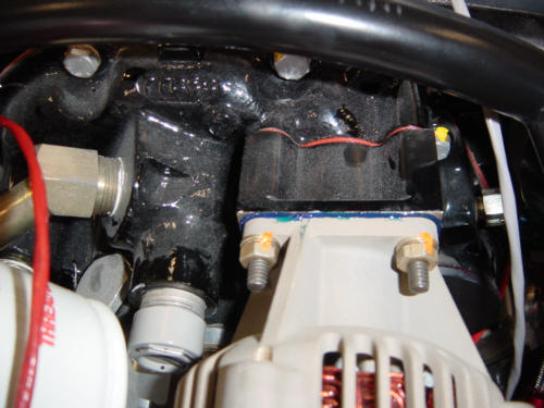
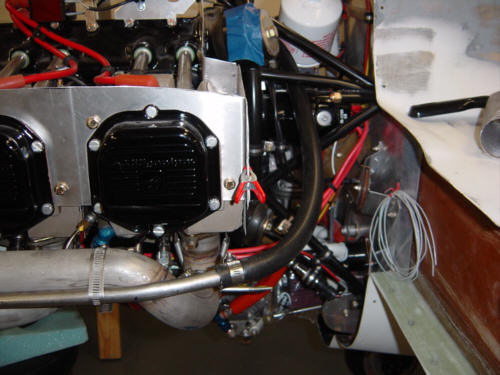
Now for some accessories. I prepped the gasket, installed and torqued the backup alternator. You will note I also marked each nut with torque paint to indicate that it was done and to help identify any back-off in the future. After that was in, I made up a short piece of flex line and mounted the oil pressure sensor. I'm not sure where the fuel pressure sensor is going to go just yet, so I'll hold off it for now. While I was in the area, I hooked up the magneto harness and ran the lower spark plug lines. On the top side, I mounted the electronic ignition coils and ran the wires back through a grommet in the baffles. Still need to run the trigger wires to finish up the ignition...very soon, I promise.
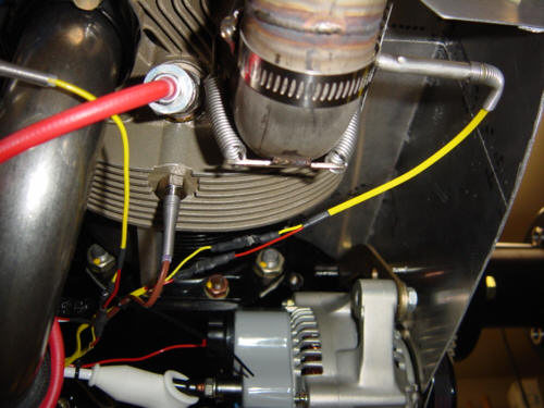
Aside from taking off and putting the engine back on by myself, I spent the most time installing and running the wires for the Cylinder Head Temperature (CHT) and Exhaust Gas Temperature (EGT) probes. The one with the brown wire is CHT, and the yellow is EGT. They route up under the engine, bundled onto the firewall, and terminate at the engine monitor data processing unit. I'm jazzed!! I can almost hear the thing purring!
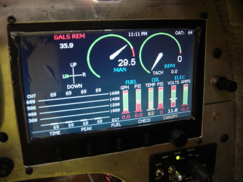
UPDATE 3-7-04: I installed the fuel pressue sensor on the bottom right side, close to the fuel line. This was the last of the engine and monitoring sensors and now my ACS2002 engine monitor is showing all the bars and graphs. Yippie!!
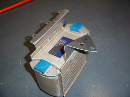
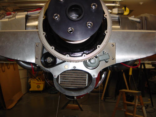
This was an interesting part of the engine installation as there were no bracket templates, no suggestions for placement, and not many pictures available for the 360 install. So, I was on my own to figure out how to mount the oil cooler under the engine in between the oil sump and the accessories. Complicating matters, the fuel spider was already mounted there and I didn't want to have to move it unless I absolutely had to. First, I took some poster board paper and experimented with different bracket shapes until I came up with a couple that worked. Next, I used the paper templates to cut and bend some .040" 2024-T3 aluminum into usable brackets. After some minor tweaks, I was able to get the cooler in the right position and didn't even have to modify the fuel spider at all. Notice how the aft cooler bracket had to mount to the engine at an angle...scary, but surprisingly simple to do. Once it is all done, it looks like this.
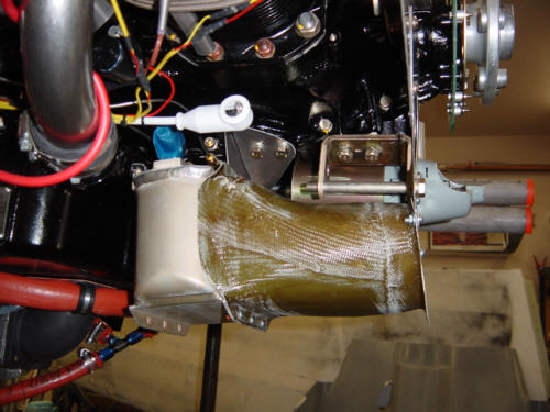
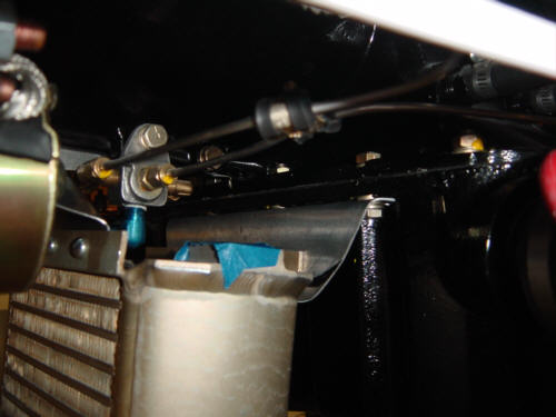
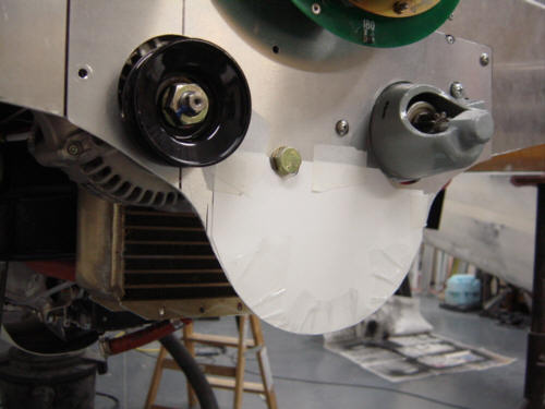
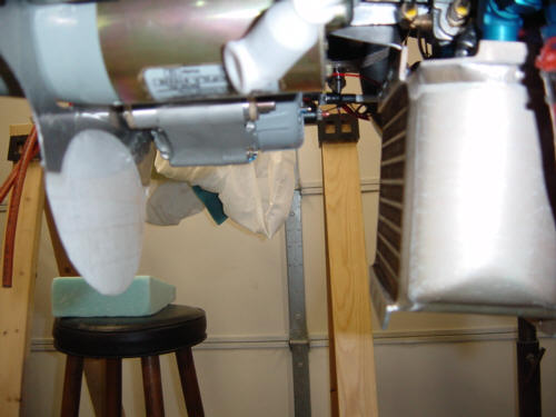
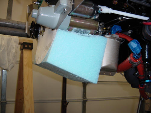
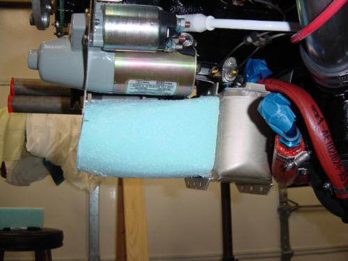
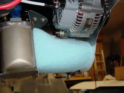
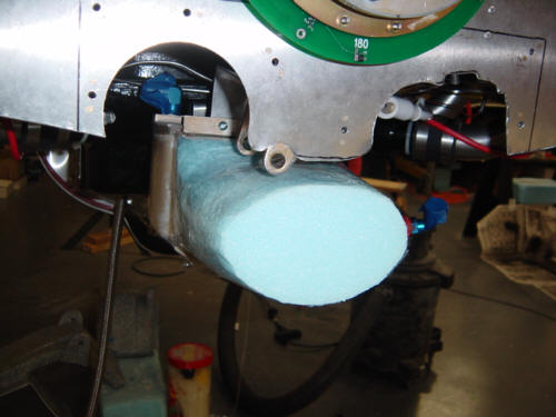
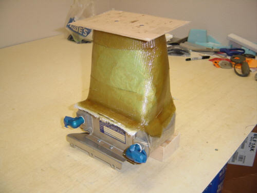
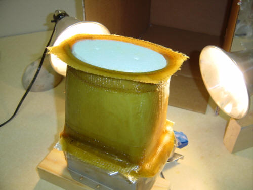
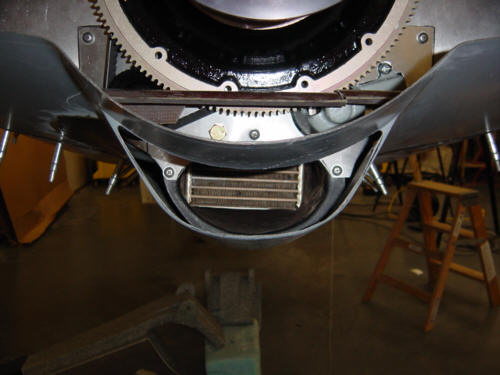
OK, now that the cooler is securely mounted, I need to make a air flow funnel to route the air through the cooler and out the aft opening in the cowl. First off, I need to make a paper template to designate the boundaries of the cowl and the endpoint of the funnel. Now that I have a point A and B, I have to "get there". Making the funnel is simple - just stick a block of foam in-between the cooler and the template, and trim to shape. Just remember to check the clearance of all the accessories, like the alternator and more importantly, the nut on the end of the bracket. You see, you have to not only have to leave room for the accessory, you have to be able to service it, get to the nuts and bolts, etc. Tricky business this is! After I finalized and TRIPLE checked the shape for fit, I wrapped the whole thing with packing tape as a mold release and removed the entire assembly for glassing.
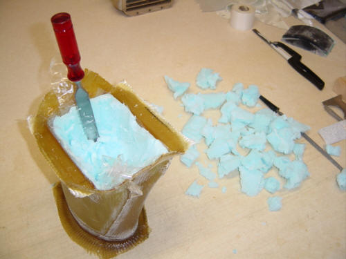
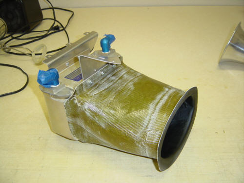
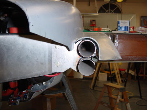
The funnel was constructed with 4-plys of BID glass for the body, and additional plies for the mounting tabs. The tape covered cardboard was used to make flanges on the aft end. Once fully cured, I dug out the foam, trimmed and connected it and put it back on the engine. I also primered and painted the interior of the funnel as you can look down into it from the rear of the plane. But before you can do that, I had to cut the opening in the aft cowl. This opening sits just below the spinner and serves as a dedicated hot-air exit port for the oil cooler. VIOLA!!! Est Fini!!
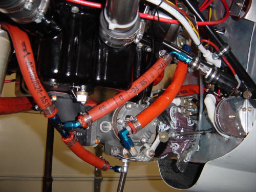
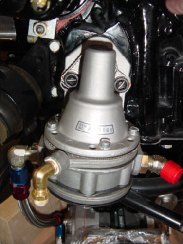
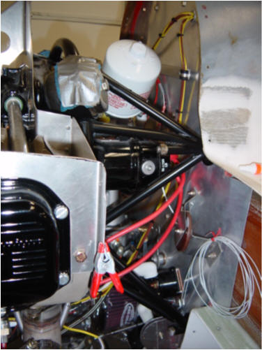
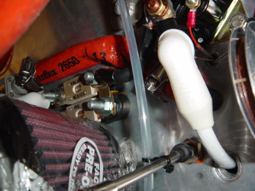
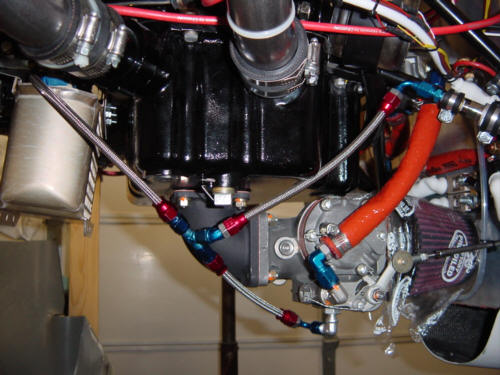
We have now covered two of the three things an engine needs to make power - Ignition source, and Air. The third...fuel!! You have seen in the other components of the fuel system inside the airframe, but now we will cover hooking it up to the engine. As you remember, the fuel from the tanks is run through a fuel valve and electric pump in the front of the plane. It travels through a filter and penetrated the firewall next to the rudder pulley. From there, I ran a firesleved tube over to the gascolator. A gascolator is another filtering device that separated debris and water from the fuel. From there, it flows through a firesleeved flex line to the mechanical fuel pump. This is the main pump, as the electrical pump is for system priming high flow boost, and emergency use. There is another firesleeved flex line that runs down to the Fuel Injection Servo. The servo meters the flow of fuel to the injectors and keeps the air/fuel mixture at the correct levels. A quick note - the orange firesleeve is made of silicone and glass cloth. It covers the hard and flex lines and keeps them protected from flame shoud a fire erupt in the engine compartment. They are expensive, but well worth the few extra minutes that might save your life! A must for my plane...regardless of cost.
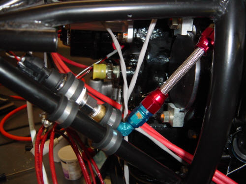
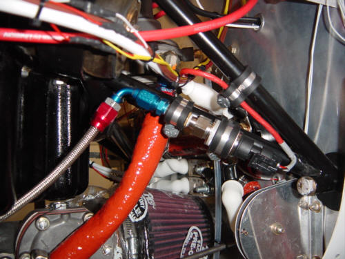
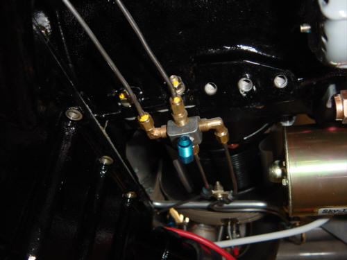
From the servo, the smaller flex line runs up to the fuel distribution spider where it is evenly distributed to the injectors in each cylinder. These lines also get firesleeves...after all, they DO carry fuel! The tee in the middle runs over to the fuel pressure sensor secured on one of the engine mount tubes. (Note: the pressure sensor should not be connected here, it was moved to the servo fuel feed line right after first start.)
Wow! Another completed section! This is so cool...to finall write those words...and mean it!
I still had a few tweaks to do with the engine before first startup. Mainly the exhaust needed to be supported, a breather tube mounted, and everything needed final torque and safe-ties.
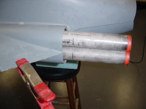
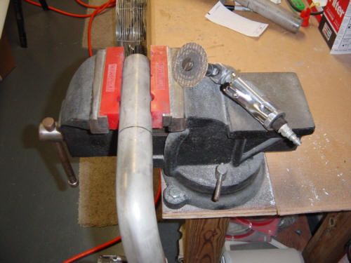
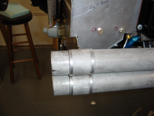
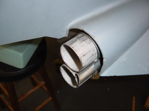
As you can see here, the stainless steel exhaust pipes were still WAY too long. Nothing a vice and cut-off wheel can't handle! I used a paper ATM receipt as a marking guide - just wrap around the tube, match up the parallel sides of the paper, and use them as a marking guide. A perfectly straight mark is generated - simple and effective. I used the cut-off wheel, and it cut the line very straight...I was actually shocked. I guess because the stainless is so stiff, it held the disk in line and didn't allow any deviations. Oh well...it worked for me, and I'm very pleased with the results. Right side and Left side pipes.
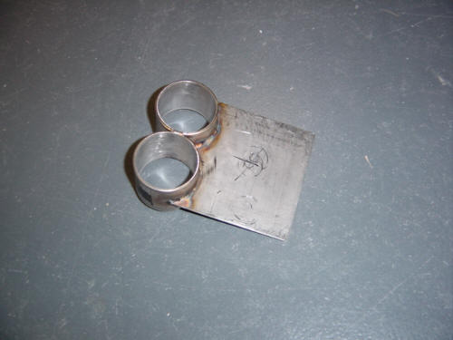
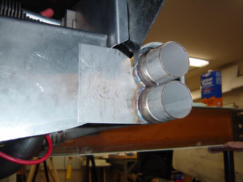
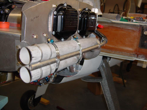
The next challenge was how to support the ends of the pipes, as engine vibration would cause them to crack and eventually break. For those of you who don't appreciate how bad that really is...let me point something out....the propeller is BEHIND the engine - if a pipe breaks, it goes through the prop with potentially disastrous results. SO...I had the exhaust guys weld up a couple of brackets. These are also stainless steel and slide over the ends of the tubes and bolt onto the aft baffles for support. Here's a side view of the bracket in place.
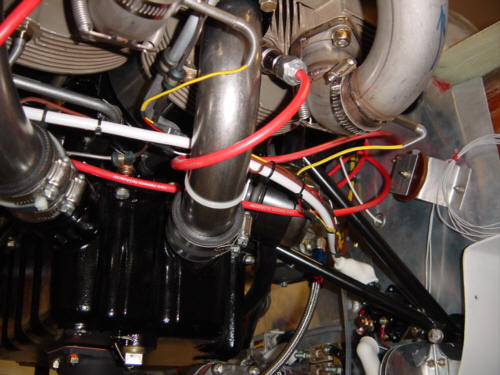
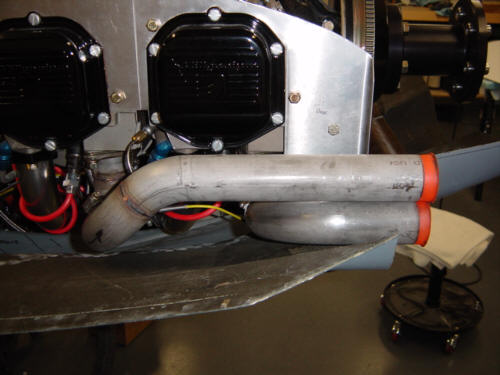
The crankcase breather tube was very easy. I chose the traditional location for my tube - running parallel to the right-side pipes. This is just a 5/8" diameter stainless steel tube that is held in place with three stainless steel worm clamps. It is attached to the breather port on the accessory case with a 3/4" O.D. MIL-H-6000 hose. The exit port sits >right next to the exhaust ports and helps vaporize the oil that vents out of the crankcase - it's the little tube in-between the exhaust pipes. I even cut the exit port at an angle....why?....because it looks kewl, that's why. Hehe!!
OK...NOW...this engine is ready to run!!! Just add fuel and oil!!!
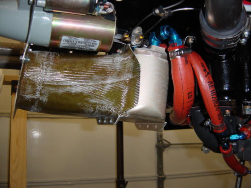
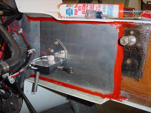
UPDATE 7-26-04: This is another one of those things I am catching up with as I prep for first flight - extending the heat shields out along the spar. I won't bore you with the details as they are the same metal/fiberfrax/RTV sandwich as before. For those that are curious, here are a couple of pictures: right side and left side.
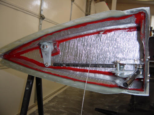
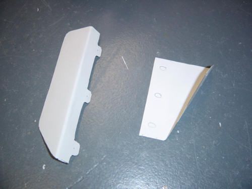
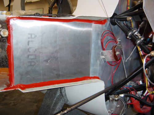
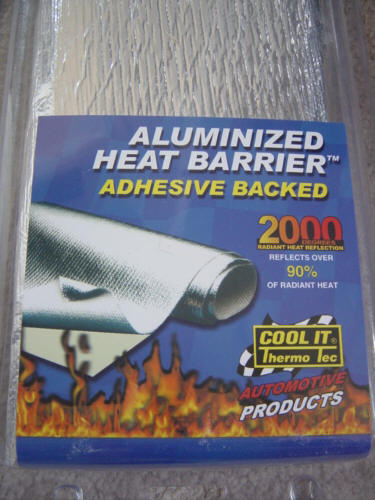
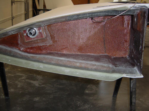
Along the same lines as the above update, it is time to insulate the wing roots too. I didn't like the clunky, "can't get to anything", style heat shield called out in the Long-EZ plans - so, it was time to upgrade and modernize. I found this stuff as the material of choice - Thermo-Tec Aluminized Heat Barrier sheets. Man, is this wonderful stuff!!! It is good for 2000 degrees of radiant heat, it's adhesive backed and is not very expensive. Good stuff it is...and I would recommend it.
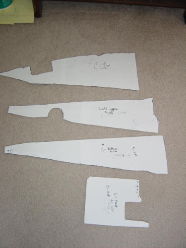
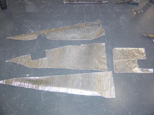
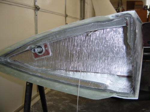
I started out by taking everything out of the wing root. I then took a couple of sheets of paper and made some templates from the inside surfaces. Being careful to get the aluminum side out, I transferred those templated to the shield cloth and cut them out. Installation was a snap - just remove the backing from the adhesive, and stick'em to the wing root surfaces. It fill in the seams and to make sure no oils/water gets under the aluminum barrier, I filled the joints with high temp RTV silicone sealant. Ta-da! Everything re-attached and the job's done!
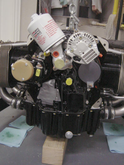
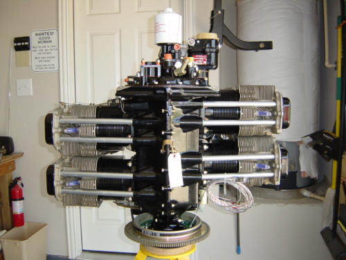
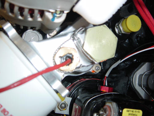
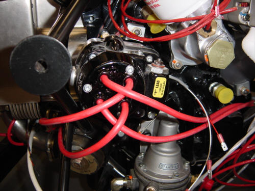
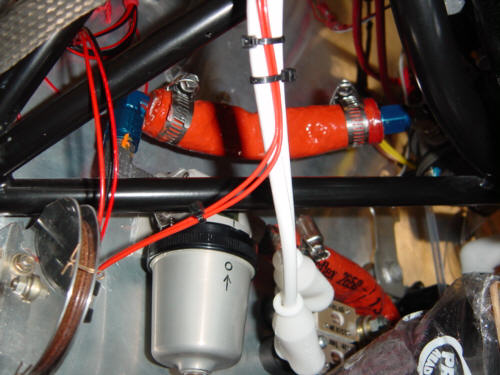
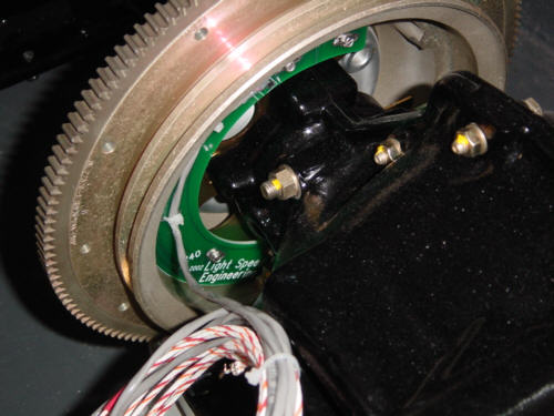
Being that is was my first engine to be fully accessorized and first one to ever be installed - naturally, I had a few problems. The fist thing I added was a simple tachometer drive cap. (the little gray cap in the middle) It simply covers the tachometer gear drive port to protect it since I'll be using an electronic ignition. Specifically, I'm going with Klaus' Plasma II+ ignition - and the timing pick-up sensor plates are already installed.
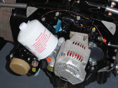
Second, the straight 'spin-on' oil filter adapter did not clear the firewall. This was easily overcome by replacing it with a B&C 90-degree oil filter adapter. It's a rather expensive little part, but it is well manufactured and will make changing the filter much easier. The major bonus was when Aero Sport Power offered to take the old oil adapter back for a full refund. Now THAT is customer service. I'm telling you flat out - these folks are top-notch professionals before, during and after the job is done! If you look closely, you might also notice that I had to change around the oil-cooler line fittings so that the line will now clear the repositioned oil filter.
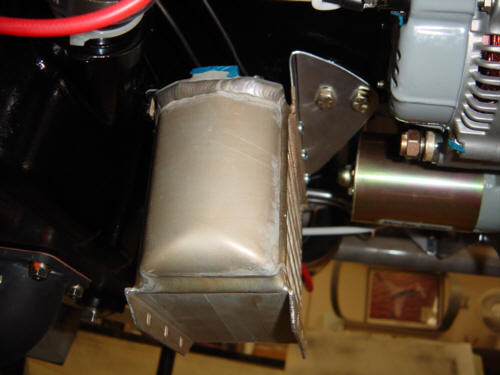
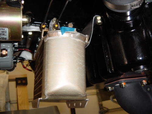
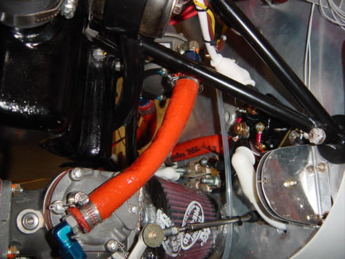
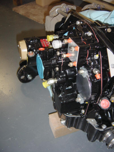
The biggest problem I encountered was a flaw in the pre-manufactured engine mount. This engine mount was sub-contracted to a company in Kansas by Dave back in the Renaissance Composites days (years ago). The problem is that the lower mount tube that connected the lower isolator cups is in the WRONG position. It is positioned too high up on the accessory case and interferes with the bottom of the fuel pump by a full 3/4-inch!! Dave has agreed to cut and re-weld the mount and I'm told there were several others that were incorrectly manufactured by the same guy. So, no fuel pump for awhile...(hence, the duct tape cover)
Next, I added a B&C 20-amp backup alternator on the vacuum pump pad. This is an important modification for an all-electric airplane. You'll read more about this unit during the wiring and avionics install sections in the future. In short, even with primary alternator failure, I will still be able to run all the important goodies without taxing the battery. Then use the battery reserve for the 'last-mile' when extending the gear, running the aux. fuel pump, etc. Yeah!
With the new parts installed, here is what it looks like mounted to the aircraft.
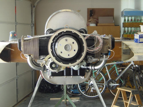
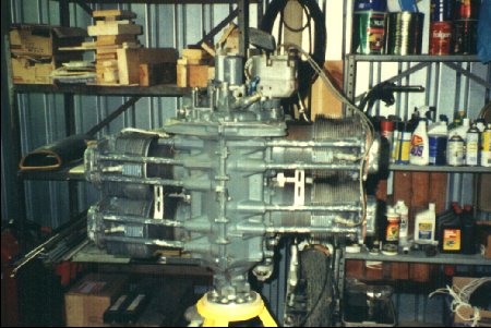
Some back story: Many years ago, I purchased a 0-time Lycoming O-360-A2A as a power plant for the Berkut. It was not pretty, had no accessories but was fresh metal, decently priced and in good mechanical shape. I was forced to sell that engine when the original company that produced the Berkut was forced into bankruptcy. Now, I have a completely remanufactured 180-HP, Lycoming IO-360-B2B with all the lite-weight accessories, new XP-360 parts (crank, cam, rods, 9.2:1 pistons, gears, etc.), Bendix fuel injection servo, Millennium cylinders and no vacuum pump. Besides all the mechanical goodies - it's wrapped up in a beautiful black and gold finish. The work was all done by Aero Sport Power and I have to say they did a wonderful job. Really great folks over there - easy to work with, very accommodating, and detail oriented. I would highly recommend them to anyone!
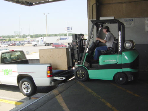
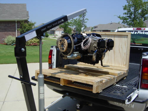
So, on July 3rd, 2003, Tim and I picked up the engine from the freight depot. Drove it back to the shop, disassembled the crate and hoisted the engine. Needless to say, this was a big day for me and a major milestone for the Berkut project for this will be the heart of the beast.
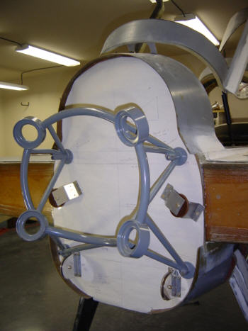
I figured with the engine coming soon, I needed to get busy on the aft end of the plane. Tim, my old hangar mate from the home town, dropped by and we decided to tackle the big metal sheet!
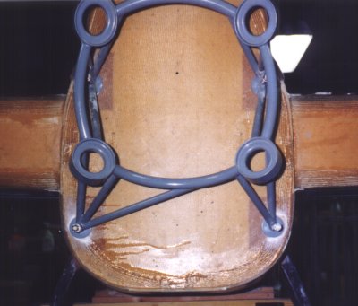
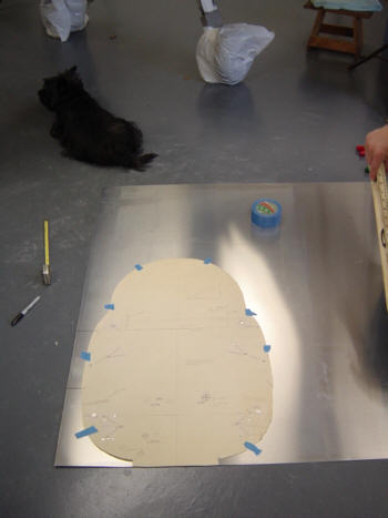
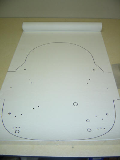
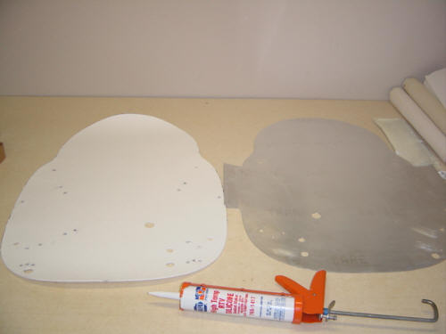
First, you place the paper firewall template on the after face and locate and position all the rudder pulleys. Double check the alignment with the engine mount, and drill the holes. Since I don't actually have the engine yet, I don't know where to position the other accessories - gascolator, fuel lines, etc. Those will be placed and drilled at a later date. Once we had all the holes drilled, we took everything off the plane and transferred the paper template on to the .020" thick 6061-T6 aluminum sheet. The aluminum is only a protection barrier for the REAL insulator (Fiberfrax) material that will be added later. Even so, this grade of aluminum is good for a whopping 1,200-degrees.
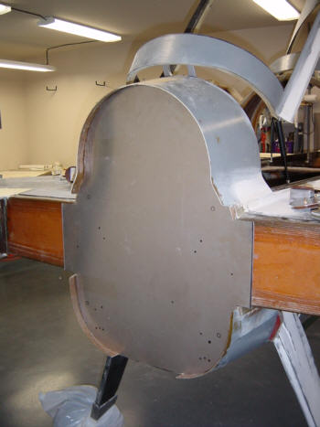
Finally, once the sheet is cut to shape, the firewall shield is fitted to the aircraft and the mounting holes are back drilled. Later, before the engine is attached, we will add the Fiberfrax insulation. It is best to wait as long as possible to keep the insulation from being contaminated with oils, dirt or dust. Meanwhile, here is what the mock-up attachment looks like.
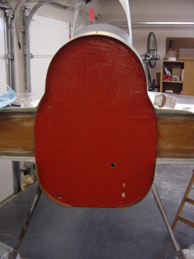
(Time Passes) Now that the engine has been mock-installed and other items like the gascolator have been positioned, it is time to install the Fiberfrax insulation. To do this, everything has to come off the firewall so the aluminum sheet can be used as a template. Border lines and holes are transferred to the Fiberfrax and all the hole are cut out and cleaned up. To assure that the Fiberfrax is completely protected and captured in-between the aluminum and the fiberglass firewall, high-temperature RTV silicone sealant is used. First, a layer of RTV is spread over the the entire fiberglass surface. The Fiberfrax is put on and pressed onto the RTV sealant. Then the same thing is done to the forward side of the aluminum shield and it too is pressed onto the Fiberfrax. All the brackets and engine mount are reattached to the firewall to help squeeze everything down - a clamp is used at the top as there is no hardware attached up there just yet. To complete this installation - a bead of RTV is spread around the perimeter of the aluminum to make sure that no oil or contaminates are absorbed by the Fiberfrax. Voila! A 1200+ degree @ 15+min firewall.
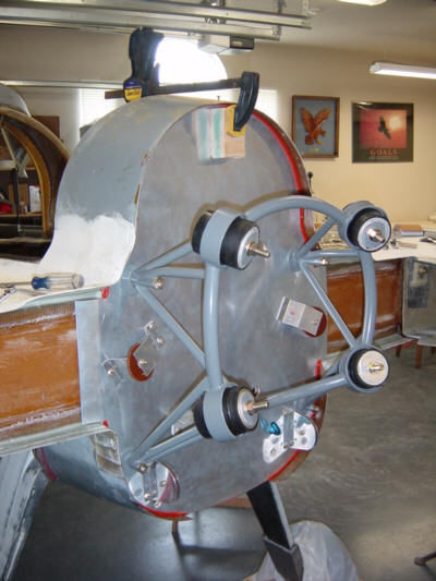
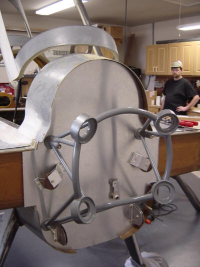
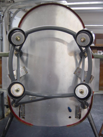
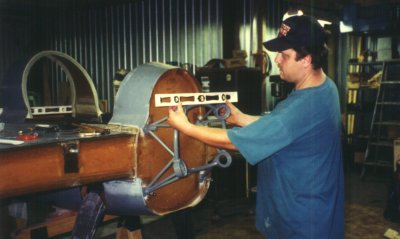
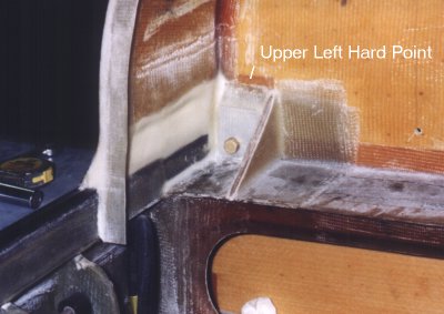
The final act performed in the "hometown" hangar was to install the engine mount. While the plane was still jiged into perfect level, Tim and I positioned the engine mount on the centerline and made sure it is level. The Berkut is a symetrical bird - without the body of the aircraft in the propeller slipstream, there is much less power-induced yaw. So, it stands to reason that the engine will be mounted on dead center-line. In this picture, you can see the other side of the firewall and the upper left-hand hard point for the engine mount. It is difficult to see but the sandwich of aluminum, glass, phenolic and flox is more than an inch thick!
There is much more to do here (obviously), but I have not pregressed down that road just yet. Please check in from time to time as I will be posting more in this section as work is completed.
 Back to the Proto-page