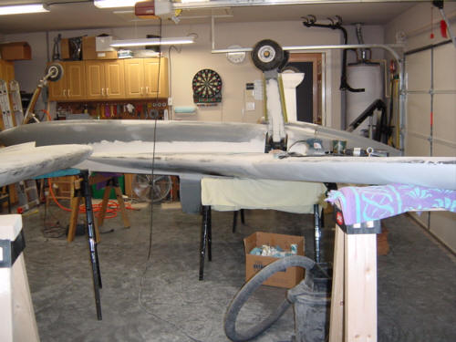
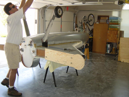
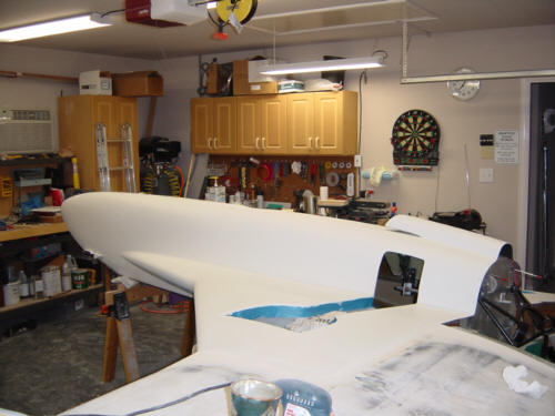
In order to do the filling, conturing, fairing, and primering of the underside of the plane, it is best to completely invert it rather than pulling a Michael 'Angelo. So, I put out the call to my Texas Berkut brothers..and they came to my rescue! Many thanks to John Mauro #058 and Wayne Arendsee #003 for coming to my aid in flipping the plane! Guys, I could not have done it without you - especially since all my other "friends" bailed on me! (...time to cancel Christmas for some people!) The job went well with only 4-people and everything is very stable for sanding and prep work but having a fifth person would have really been helpful for sawhorse placement.
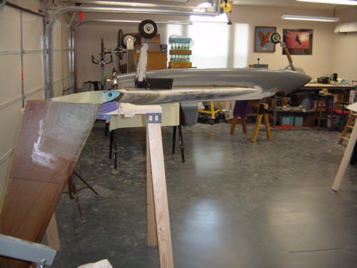
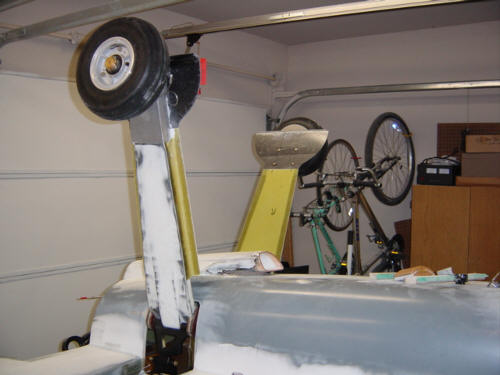
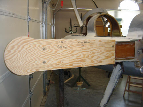
I started by making a roll-over jig that attaches to the bolts that mount the left wing onto the spar. It's 3/4-inch plywood and plenty strong enough for the task. With 2-folks on the aft end, and the other two on the nose, the fuselage is tipped over onto the round part of the jig, and slowly rolled 90-degrees over on it's side. Once there, personnel shift to new positions as it is rolled the rest of the way. We then carried the fuselage into the garage and set it down on sawhorses under the strakes and nose.
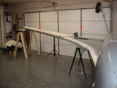
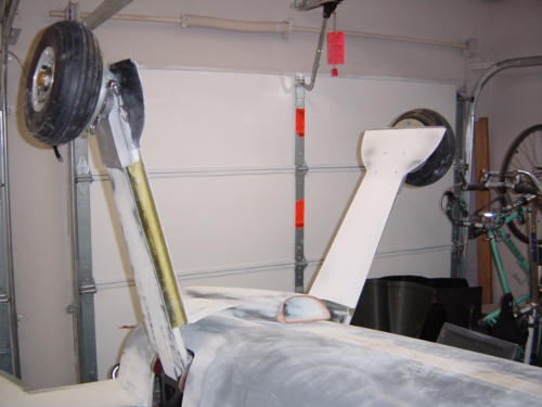
A complicating problem was discovered - with the winglet upside down and canted outward (because the fuselage is at an angle to clear the winglet) it would not fit in the garage in a front to back. I originally wanted to be able to open the garage door and put the other wing on at the same time (like before) so the cowls can be faired in at the same time. No dice...gotta do it one side at a time since I can't put both wings on. So, lengthwise it went...one wing at a time. NOTE: For those canard builders out there without winglets attached - wait until AFTER the bottom prep is completed to install them. I installed mine 7 years ago and am paying the piper now. Things would have been MUCH simpler if I didn't have to jack-up the wing so that the winglet can clear the floor.
I forgot to include that Scott Charlton (forgot your number) happened to be in town and stopped by for a visit too...just in time to miss the work. (great timing Scott!) ;-) It ended up being the first TBBA meeting - Texas Berkut Builders Association, that is. Now that Scott will be moving even closer to the rest of us in the Dallas area...we may even have to make this a regular meeting thing since we will all be within 50 miles of each other. ("next door" in Texas terms) We certainly took vows to actively help each other complete our planes! Very kewl!
So...on to the work. Detailed below are all the little jobs that make up the bottom finishout. There is nothing really exciting here, but these little jobs add up to alot of time spent on the side that few people even look at. Here are a few of the highlights - keep in mind, these projects are all over the bottom of the plane...
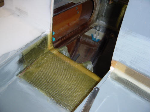
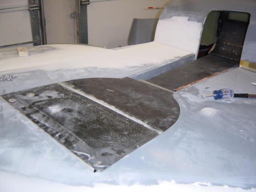
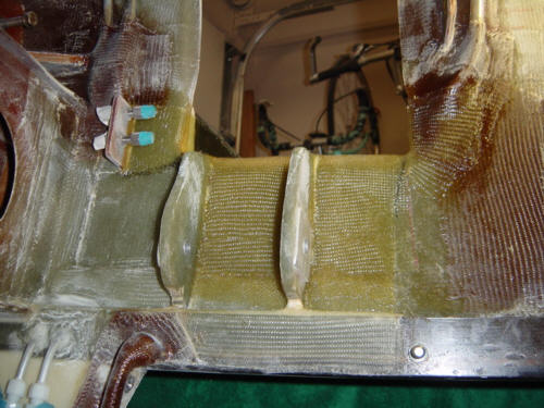
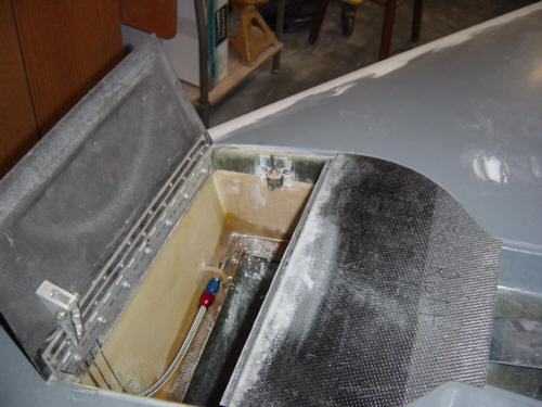
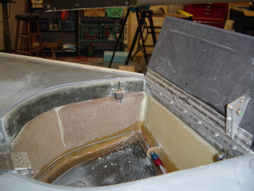
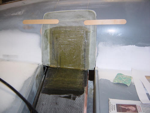
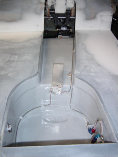
This is the intersection of the strake depression and the fuselage where the gear leg comes out. If you have been paying attention, you will remember the big BID lay-up on the inside of the strake tank in this area. It's an important area as the upward forces of the gear leg are spread out into the strake and fuselage side wall. It consists of an 8-ply UNI lay-up running from the strake depression to the inner fuselage wall. Then the whole thing is covered with 2-ply BID. Another reason this area is important is shown in the next section below - over center pivot support.
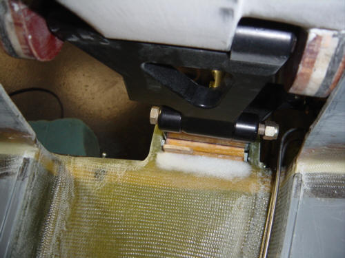
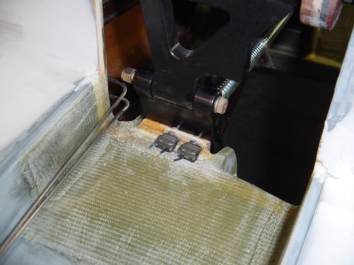
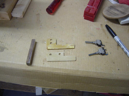
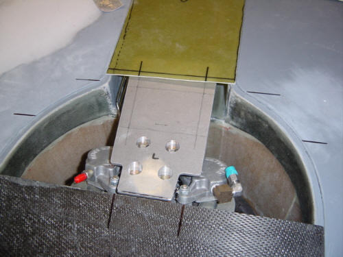
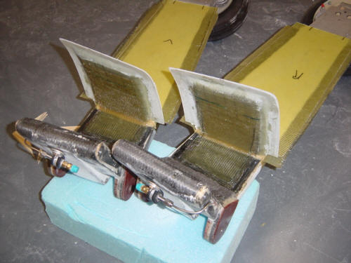
The main gear pivot arms have a machined 'elbow' that only allows a certain amount of travel. It was later discovered that after a few years, this 'lock' would slowly wear down and allow the gear to spread outward. To prevent this, and to strengthen the whole assembly, a modification was recommended to add a 3/8-inch thick phenolic and flox pad for the arms to rest against. You will also notice, there is a 1/8-inch phenolic tab in the flox sandwich. This is used to mount the gear position switches. These are detailed below...
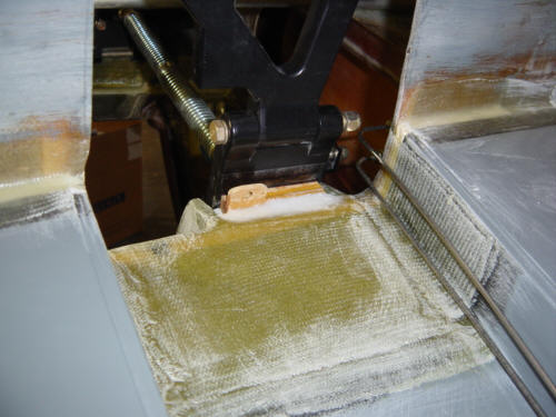
These switches will be wired into the gear position lights and throttle/gear warning systems. They are all momentary contact, single pole (one switch), double throw (two positions). They can be used for both sets of logic - ON when depressed, or OFF when depressed. I'll talk more about this in the wiring sections to come.
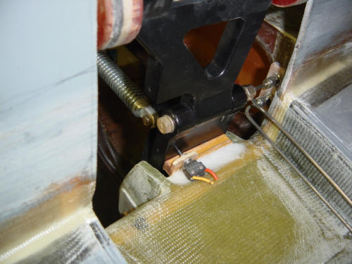
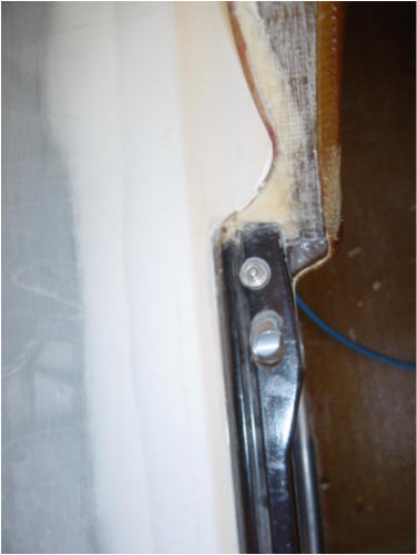
The nose gear is a little different since the actuator has some built-in sensors so we'll just look at the main gear here. I mounted the switches in the following positions: Main Right - Down-lock light (shown above), Main Right - Up/Safe light, Main Left - Up/Safe light and with some difficulty, the Main Left - Down-lock light and Gear Extended sense. I had a little trouble with the last one....this was an 'Oops!' moment and will surely will not be my last.
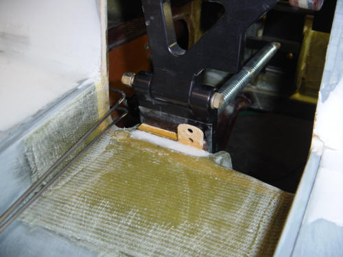
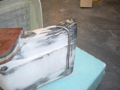
My original plan was to just extend the phenolic tab to accommodate both switches in piggy-back position...and that is what I first installed. Can you guess what the problem was? Yep...it didn't clear the gear leg!! Duh, right? You would be amazed what your mind overlooks when it's focused on doing something. Oh well, nothing but a little wasted time. I cut the tab and phenolic pad off of the plane and shaped a new tab this time in a tandem configuration. This time, I got it right!
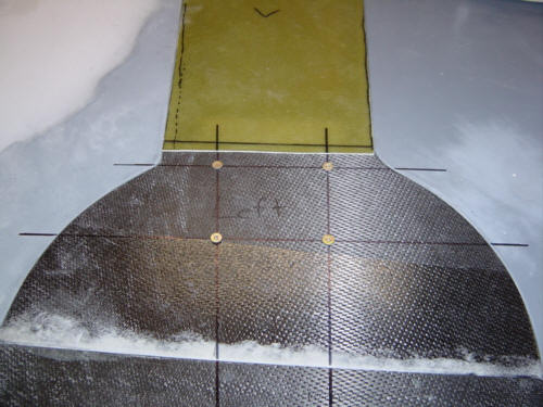
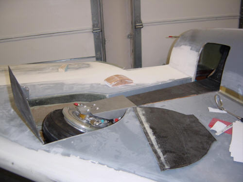
The middle gear door is actually the crescent shaped carbon structure shown above. It is simply trimmed down to the correct fit inside the strake's depression and mated to the outer gear door. One thing I had to do first was to carve out a little extra room in the gear well for the enhanced Matco brake assembly. To allow the gear leg to retract about an 1/8-inch more, I cut away the inner layer of carbon and foam where it interfered, transitioned with flox and covered with 2-ply of BID. Now, I have no need for an external blister on the outer gear door.
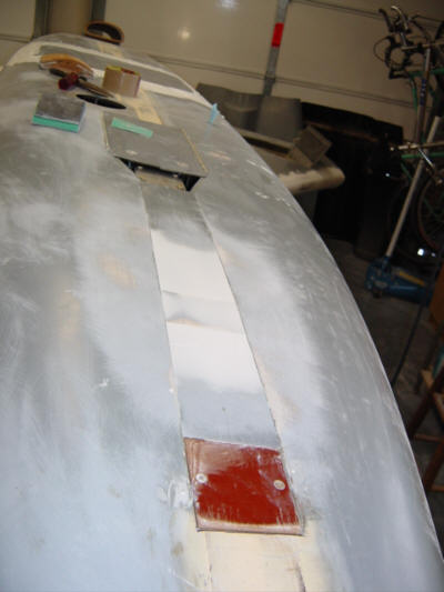
The main gear doors and fairings are made of 4 parts (inboard to outboard) - the inner door, leg fairing, middle door, and outer hinged door. The outer gear door was installed with the hydraulic systems so now it is time to finish up the others. I started with the main gear fairings and the night before, I made some 10x20-inch 3-ply glass BID flat stock. This was then cut to fit perfectly in the gear depression lip and butts up against the top of the middle door. Once fitted, the fairing is put aside for a while.
Before the fairing can be installed, the inner gear door must be mounted. Dave did a great job reproducing kit parts that fit, right out of the box - so this was really easy. The oversize gear door was placed into rough position with a light shining from behind. This made it easy to find the exact trim points based on the actual fuselage hole. Once cut and trimmed and held in place with tongue depressors, a 8-ply BID lay-up is added to solidly attach the door. This is the initial attachment, more will be added later to the inboard side.
The middle gear door is not bonded to the leg - it is held in place by 4-screws. This allow the axel bolts to be accessed easily for maintenance. The position of the desired screw holes is first scribed on the gear talon, then transferred to the strake. Then, when the door is back in place, the marks are connected and holes are drilled and tapped. Release tape is attached to the talon and a flox pad is added to the underside of the door to remove any play when tightening the screws. Now that the inner and middle doors are in place, the gear fairing is attached to the gear leg with micro filling the gap.
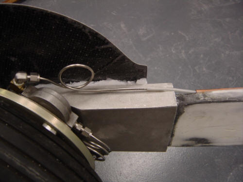
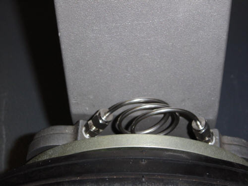
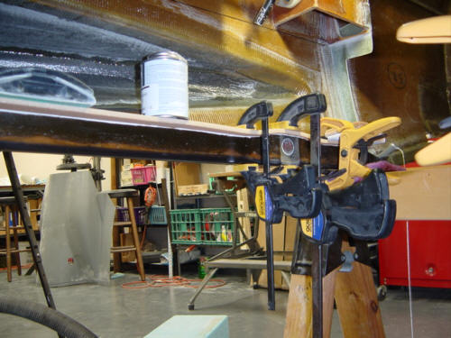
During this process, the brake lines are also installed. There are two hard lines installed on each gear leg - the feeder tube and the caliper transfer tube. Both are 1/8-inch stainless steal tube with Swagelok stainless compression fittings. The top end of the feeder tube will be attached to a flexible line and is sleeved with a Nylo-flex tube as it runs down the copper conduit in the gear leg. Because of the tube's stiffness, it is necessary to include service relief loops. This allows the calipers to move around the rotor disk without undo wear.
To complete the legs, 8 more plys of BID are added to the inboard side the of the inner door, and 3-ply tapes are added to the edges of the fairings to further attach them to the legs. Then, all there is left to do is fill and sand them and fair them into the strake bottom surface. Oh, joy...
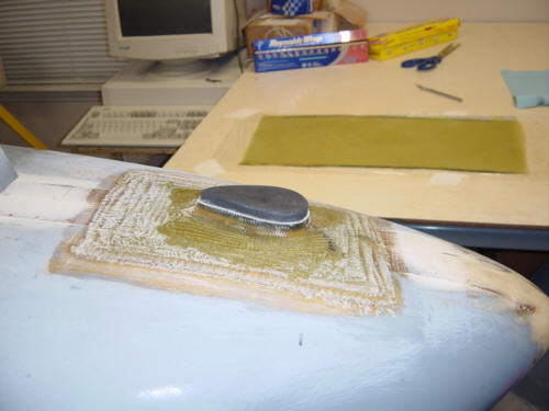
As most of you know, canard style aircraft spend much of their ground time grazing on their nose. The reason for this is simple physics - the engine is in the rear of the plane, so when the pilot steps out, the nose is lighter than the aft end. And we all know that happens when the fat kid sits on the other end of the 'see-saw'. So, we all install nose bumpers on the noses as not to damage the fiberglass airframe. Being as it's rubber, it also acts as a good parking brake.
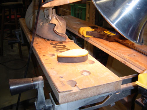
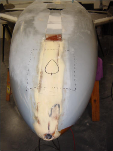
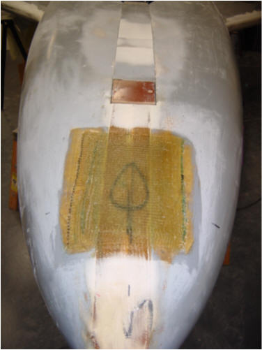
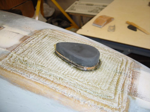
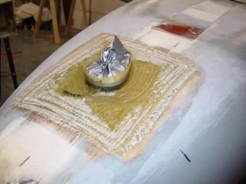
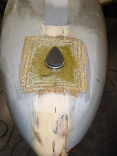
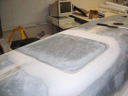
I chose to use a hockey puck for the rubber donor because it is the perfect density for what we are trying to accomplish. A band saw was used to cut a tear-drop shape out of the puck. It was belt sanded down to 5/8-inch thick and rounded on the edges. A 1/8-inch thick phenolic pad was bonded to the rubber tear-drop with the help of some relief holes I partially drilled into the rubber (flox rivets). The fuselage was sanded and prepped for a large lay-up that is designed to spread the load from the bumper evenly across the nose. 8-plys of BID are bonded to the fuselage with progressively smaller plys so that the curves of the fuselage sides are not adversely affected. While semi-cured, the bumper assembly is floxed to the fuselage pad. Then, a 2-ply BID tape is added around the perimeter of the bumper to help strengthen the mounting even more. After cure and trim, the final result is an attractive tear-drop bumper fit for a...well, Berkut...of course.
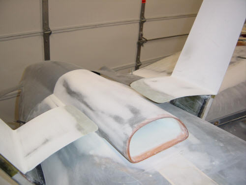
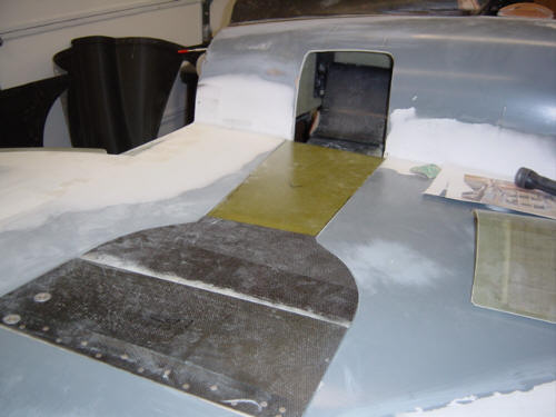
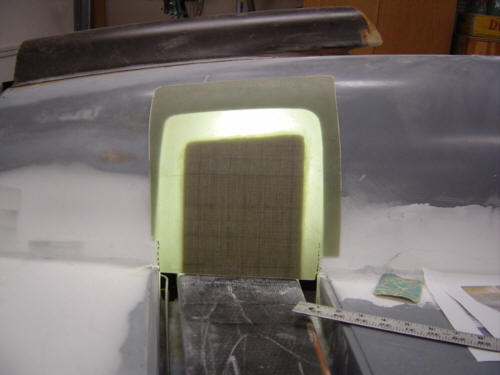
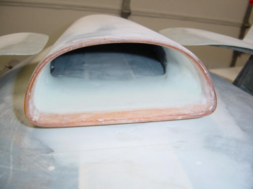
The bottom would not be complete without the 'Berkut-esque' center air scoop. This scoop will provide ram air to the engine and by-pass air for the oil cooler. The first step is to flox the scoop into place using the lower cowl as a guide. Note that inside the scoop there is a sharp drop-off. Left as-is, this drop-off acts as a type of air dam as it causes a 'trip' vortex in the incoming air. With the three total scoops, this drag adds up to as much as 5-7kts. of speed loss according to a very well known aerodynamic, canard driving guru. So, needless to say, I took great pains to fair the intake into a smooth transition. We'll have to keep our fingers crossed on the speed figures for now.
Mix, fill, cure, sand, sand, sand, repeat! Weird thing here�you'll hear much about this, but there really is not much to say about it. Lets cover the high points: I repaired the nose gear fairing from when I retrofitted the actuator, faired in the nose bumper, I matched up the belly brake, mated and transitioned the left wing/cowl/fuselage/strake interfaces, and then it happened...I ran out of West systems epoxy! Crap! So, I guess I'll have to take a break from sanding...darn. ;-)
With my break completed...and new West resin secured...I finished up the gear leg fairings and center scoop on both sides.
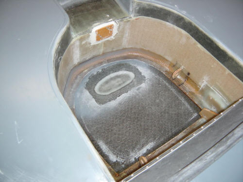
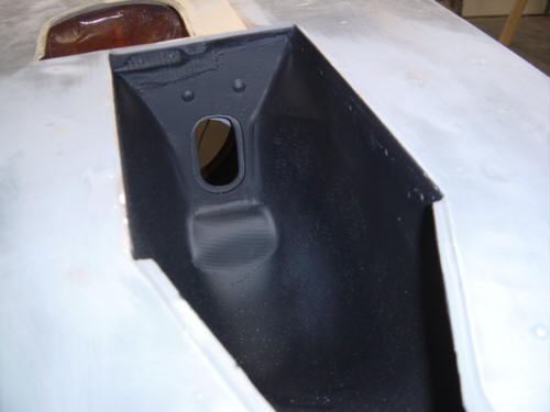
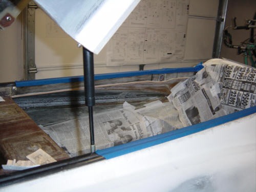
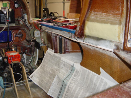
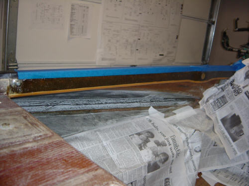
I also did a little finish up with the gear wells. I spray primered and painted the nose gear well with a semi-flat black. This is a utility area, but I wanted to clean it up just a little. The main gear wells were sealed with the same JeffCo 9700 epoxy sealant that I used inside the fuel tanks. I debated using Zolatone paint in these wells, but ultimately I decided to use the sealant to assure that no pin-hole leaks occur and to simplify the cleaning in the area.
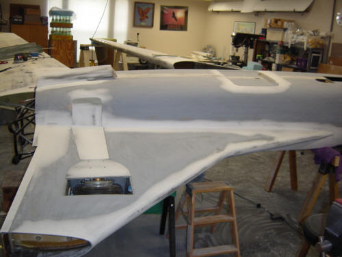
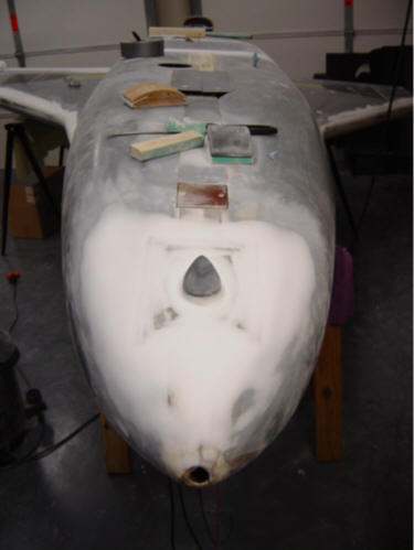
Ahhh...the last few micro sessions on the bottom of the plane! I must say that I am completely sick of sanding micro! By comparison, primer is a dream to work with...sort of. After the rest of the micro is sanded and ALL the intersections and imperfections are filled and contoured, 6-coats of UV Smooth Prime (UV protecting primer) is applied to the entire bottom of the fuselage. I chose to roll the primer on using a fine cell soft foam paint roller. It worked very well at filling pin holes and minor scrapes and dings. I applied an extra coat or two in the areas that needed a little more fine tuning on the contours. The only bad part of this process is that the surface of the primer is left rough and looking like 'eggshell' in texture. All that means is that every square inch of the surface needs to be sanded...twice - once with 150 grit, then with 220. It took me about 16 hours to sand the entire surface, but I am very pleased with the result. The primer is much easier to sand than micro, so I was able to 'cheat' a little and use the primer to fill in minor depressions. Now, I have a baby's butt smooth surface that is beautifully contoured and filled. Lots of sweat, but success at last!
I also did a few other chores while the plane was upside-down. I mounted the canopy switches in the longerons, wired them in parallel and ran the wires aft to the turtle deck. I am using the ACS2002 Engine Monitor system that also incorporates the canopy and other warning systems - complete with voice alerts. Very slick unit - you will read more about it in the instrument panel section soon. I also installed the upper versatube electrical conduits inside the longerons, and have bonded 1/4-inch PVC foam to the bottom of the longerons as part of the final closeout. Once the micro sets, the extra foam is trimmed away, and a 3-ply BID cover is added over the foam and onto the longeron and fuselage sides making a rock solid rim for the fuselage.
UPDATE 1-19-04: I finally got around to finishing up the longeron close-outs. I can't remember the reason that I didn't do it when the plane was upside-down, but it made sense back then...oh, well. So, I prepped the surfaced by taping off the upper longeron depression and sanding the entire longeron both in the front and the back. Then stood on my head, twisted and contorted, defied the laws of gravity, and tried to keep from getting epoxy all over myself like in a giant game of "Operation"....but in the process finally managed to get the 3-ply lay-ups on there. Whew! ...anyone know a good chiropractor?
So, this section is now COMPLETE! Now, as soon as I find some help...it's time to flip the plane back over for good! Another major milestone behind me...it feels very good!
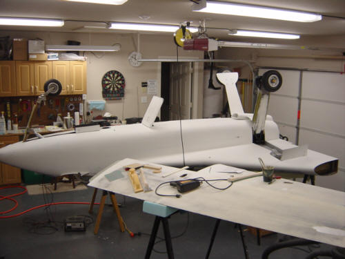
Here is what it looks like with all the parts back on, still upside-down but primered and sanded to 220 grit - FINAL PRODUCT!!!!
Oops...I spoke too soon. I knew I should not have said 'completed'...it's never completely complete. ;-)
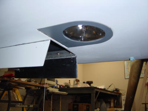
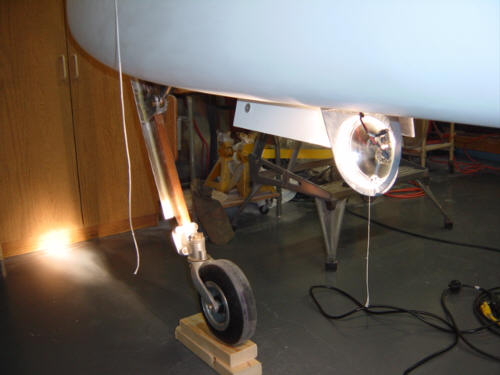
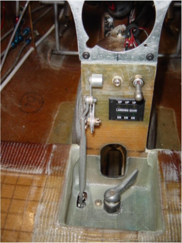
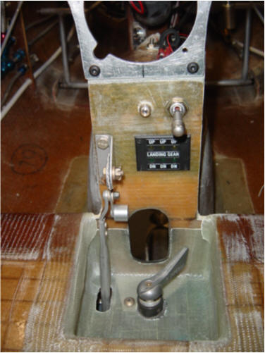
During the cockpit wiring, I realized I needed to finish-up the landing light. I went with the standard 100w GE Q4509 halogen bulb, putting out an impressive 140,000 candle power. This picture of the light in use was actually taken with all the lights out in the garage. It really lights things up and seems to be pointed in proper angle for a landing attitude. The mechanism is very simple to operate it - just a rotating lever that places a push rod over center for both an extended and retracted position. Here are a couple shots of the mechanism in the retracted and extended mode.
Now, do I dare say the bottom is done? ....probably not.
 Back to the Proto-page