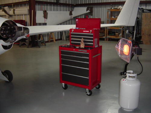
UPDATE 12-5-04: Well, I've been flying off my hours and testing quite a bit lately and I'm almost done. The weather and my schedule have not allowed as much flying as I had hoped for, but slowly the hours are coming off one my one. It's also starting to get cold and wet around here as winter approaches and the next week looks terrible for flying. Soooo, I got out the propane heater and tools and started work on the spinner install. You will also note the beautiful tool chest and portable top section in the picture. Sandy bought that top section for me after I told her that some of my tools were rusting out at the hangar because I had no place to put them. (Ain't she the greatest!?!) Sears was having a big sale so I also picked up the lower section and ended up saving about $75 in the process. In all, it's exactly what was needed out there and the top is portable enough that I can bring the important tools home as well.
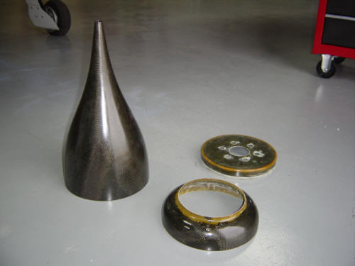
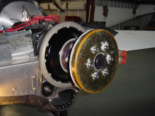
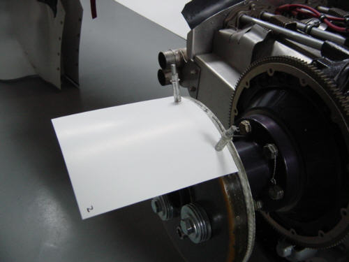
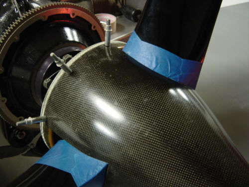
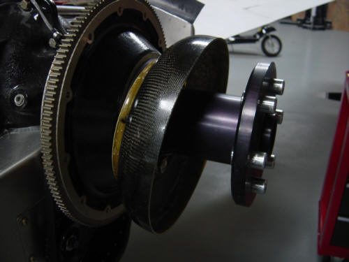
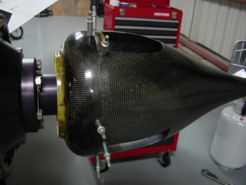
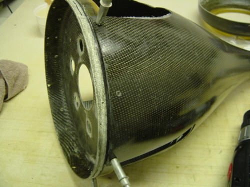
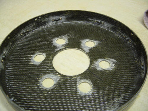
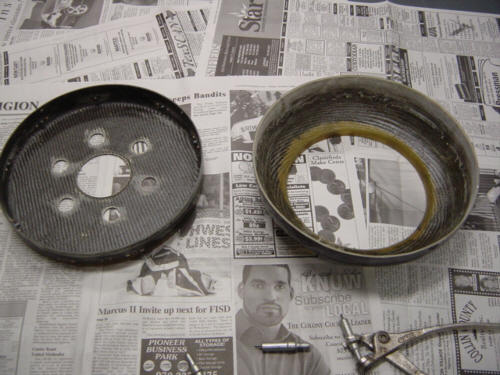
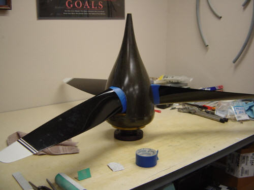
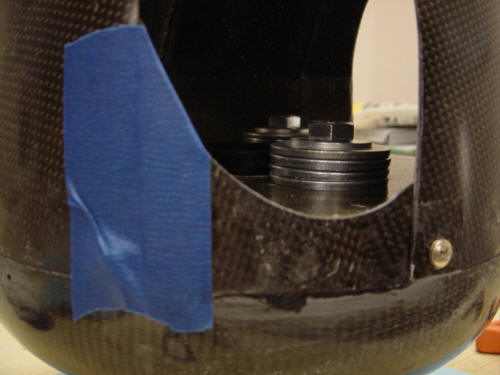
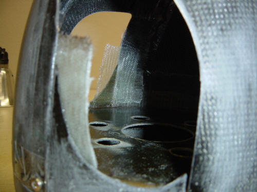
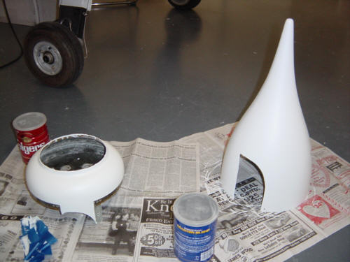
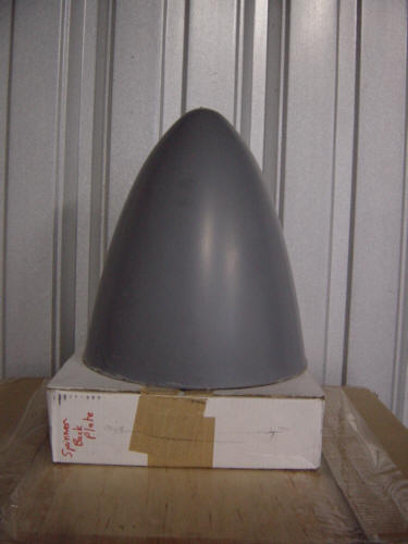
I purchased the spinner from Ken Miller, a long time Long-EZ builder/flyer and provider of parts and services. It comes in three pieces - spinner cone, flow guide and bulkhead. I took the cowl and prop off and did a trial fit of the spinner bulkhead - perfect-o! Only one small problem, the spinner dome is slightly larger than the bulkhead. So I was delayed a day while I took the assembly home and added 2-ply BID around the perimeter (as mentioned in the instructions and required for an interference fit between the spinner dome and bulkhead). The next day, I installed the propeller and used a straight edge to mark the position of the blades on the bulkhead - the marks now become the reference points on the bulkhead. Next, I slipped the spinner dome back onto the bulkhead and clamped it into place. I hooked up a starter switch across the leads of the starter relay and spun the engine over. I tapped the spinner dome until the end was spinning true with no wobble at all. While it was centered, I drilled a hole in the edge of the dome and inserted a cleco and spun it again. I continued to spin and correct until I had all the holes around the bulkhead drilled and cleco'ed. I was quite impressed with myself as the spinner remained centered and doesn't wobble at all.
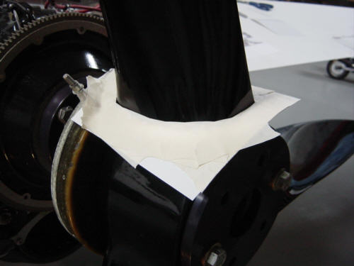
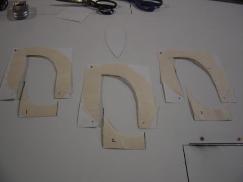
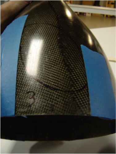
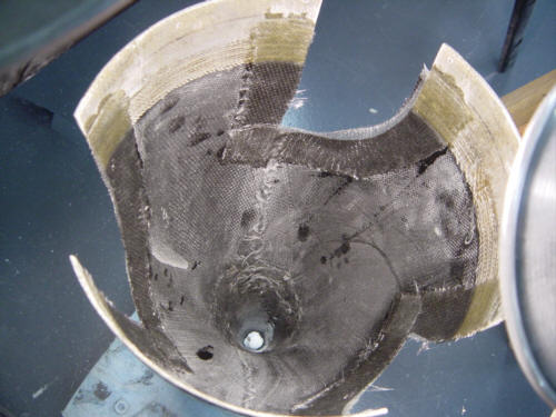
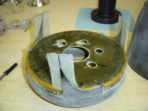
The next step involves cutting out the hole for the propeller blades. To do this, the first step is to make some templates of the propeller blades themselves. I cut out some squares of poster board and clecoed them to the bulkhead using the two screw holes on either side of each blade. I cut a hole in the center of each template roughly the shape of the blade but much larger and re-installed the propeller on the bulkhead. The template was cut oversize on purpose - I used masking tape to better scribe the arc of each blade’s front and back sides. Once the blade template was shaped, I used the straightedge and reference marks to scribe cut-lines for the blades - I have to be able to remove the spinner ya know. I repeated this process for all 3 blades, removed the templates from the bulkhead and cut out the lower sections.
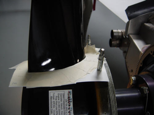
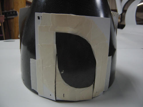
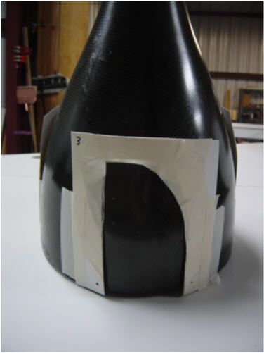
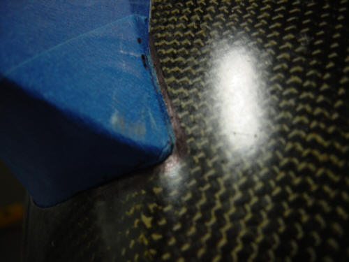
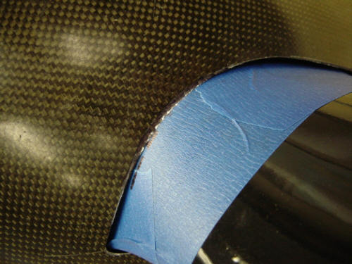
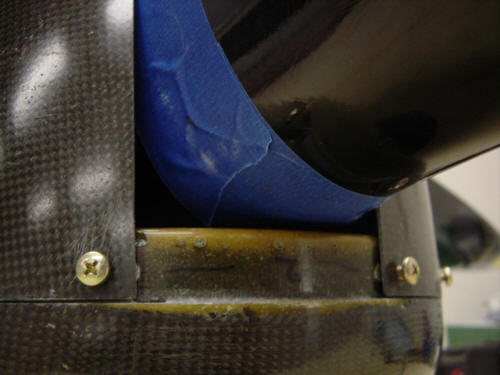
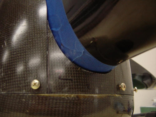
Transferring the templates to the spinner and cutting them out was easier than I thought it would be. I simply lined up the cleco holes, and taped the templates to the spinner dome and traced the inner blade profile. Then I took off the lower templates and traced the cut out lines. To aid cutting a straight line with the air-saw, I used a few pieces of painters tape to show the cut lines - black ink on black carbon is hard to see. It didn't take long to finish the cut-outs...that air saw makes quick work of composites.
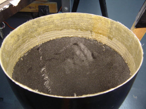
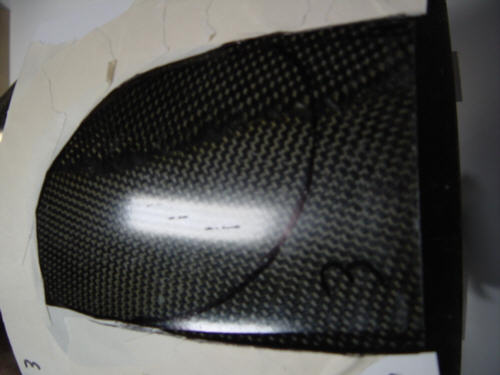
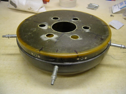
The moment of truth...did I cut the holes in the right place? One trial fit later proved that I did...whew! I rotated the propeller and marked the areas where I needed to do some more minor trimming. Once that was wrapped up, I took off the protective tape and spun the propeller and spinner together for the first time - yep, it was still centered!!! But, I still had one more thing to do before calling it a night - index the flow guide. I took the propeller off...again...and slipped the flow guide over the extension. I put the bulkhead back on with the spinner dome clecoed in place and pressed the flow guide onto the bulkhead and clecoed it in place. I spun it a few times in different positions and it never really wobbled, so I left it as it was. I took the whole assembly off the plane and took it home to lay up some 2-ply BID glass strips to the inside of the dome. I also realized I ran out of nut plates and have no screws the right size...so I had to place an emergency order. I hate “FedEx’ing” nuts and bolts...Grrrr!
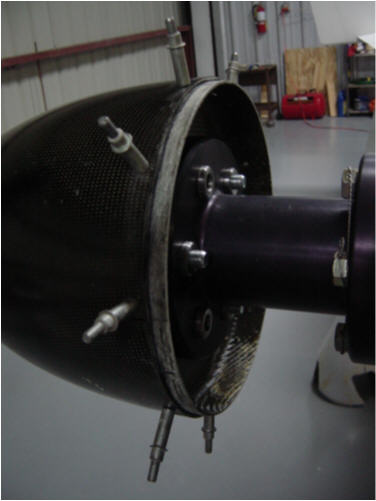
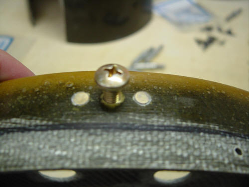
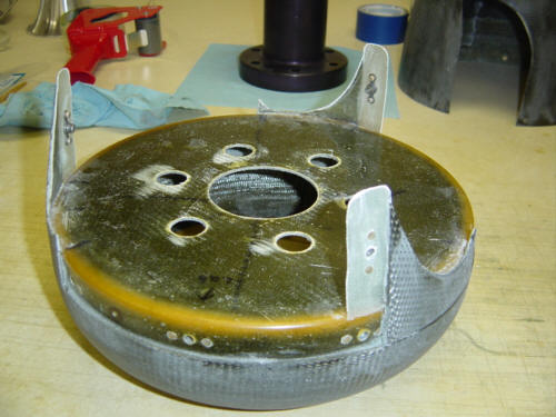
OK, now that the hardware is here, it's time to install it. The first step is to precisely drill the holes for the screws and nut plates - with clecos holding things in place, I carefully drilled the center holes only. Then I disassembled it at this point and installed the nut plates. A trick I used to install the nut plates exactly in the center of the holes was to use the nut plates themselves for alignment. I first used a screw pushed through from the inside then screwed on a nut plate, then I used one of the rivet tabs to drill the hole into the bulkhead. To drill the other, I stuck a rivet in the existing hole, then drilled the other. To set the rivets, I reversed the process...stuck the screw in from the outside, screwed on the nut plate then upset the rivets. Now repeat for the other sets of three, and...Ta da! A bulkhead of nut plates. Next it was time to bond the flow guide onto the bulkhead. This was very easy since I had already placed the clecos. I just sanded the areas of the interfaces, applied flox, bonded them together and used the clecos to hold it all in place while it cured.
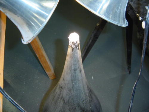
Since it was cold and wet at the hangar, I went ahead and took the propeller and extension off and brought them home to the climate conditioned workshop. I reassembled it all on the workbench and did a little more fine trimming on the spinner dome to even out the gaps. Next, it was time to cut-out and bond in the remaining parts of the spinner dome to fill in the holes behind the propeller blades. So that's exactly what I did using a little flox and held it in place with some painter's tape. After that cured, I put some packing tape on the back of the spinner bulkhead and used some BID strips to form a lip that could be used to attach the little cover to the spinner dome. A little trim, three holes and a few nut plates later and the spinner is almost ready for prime-time (pun intended). Oops, actually there is one more thing to do before primer - plug the hole at the spinner tip with a mix of flox and micro. I then sanded all the surfaces, cleaned them with a damp cloth and rolled on 6-coats of SmoothPrime UV primer. No magic here...same as the rest of the plane.
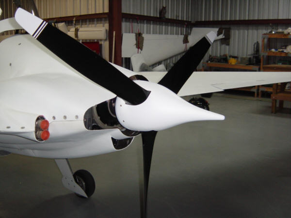
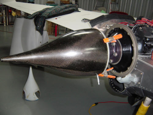
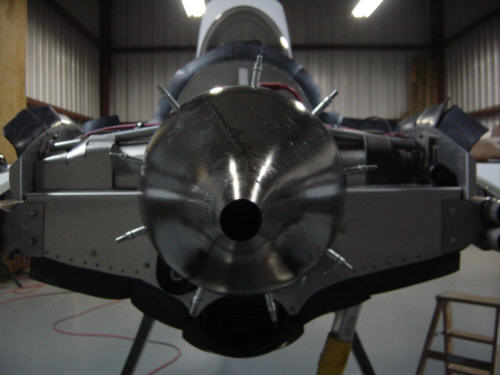
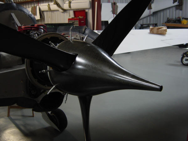
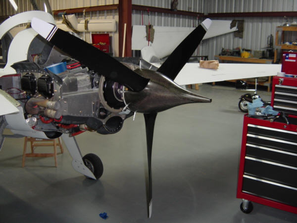
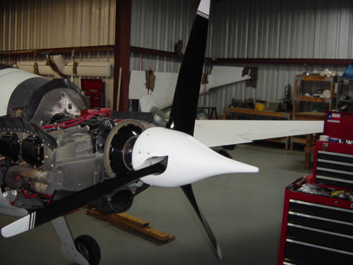
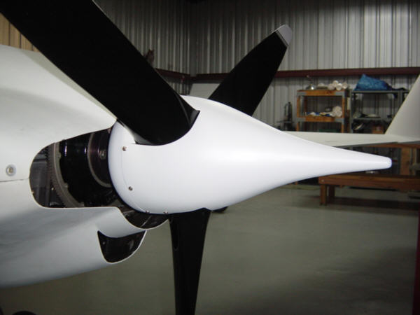
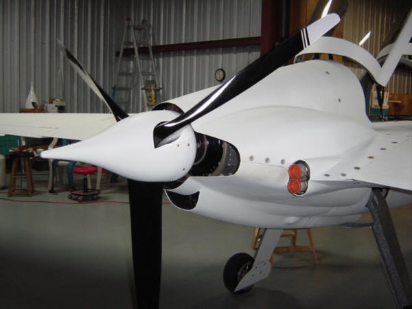
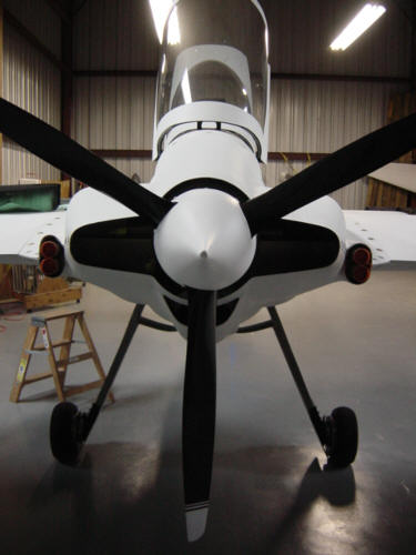
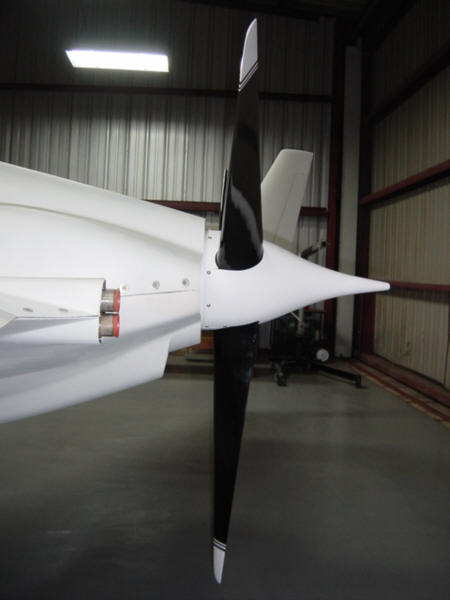
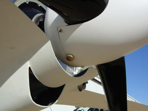
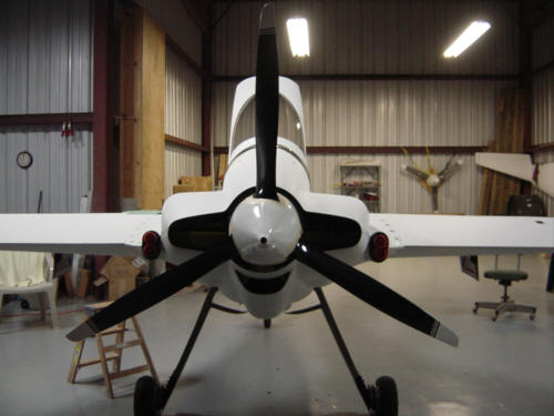
Now for the FUN part! I took the spinner back out to the hangar and INSTALLED IT for the first time. It looked good...but it looked even better with cowls back on!! Neat-o! Something about the look of that spinner I really like. Let's do a walk-around, shall we...right side, directly aft, left side view. See, I knew you'd like it too.
I have not yet flown with it yet, so I have no performance data to report...but I know the plane just gained 15 knots of "ramp speed"...as I'm sure you could see yourself. ;-)
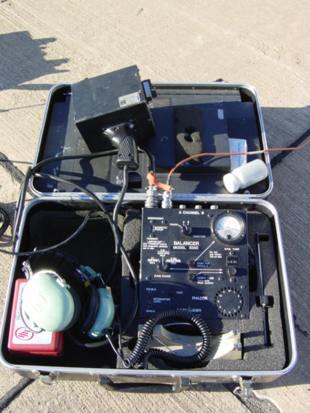
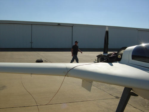
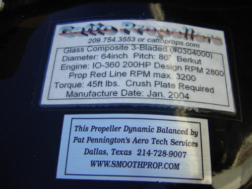
UPDATE 12-17-04: Now that the spinner is installed and proven, it's time to make sure it's in balance. I've been wanting to have the propeller dynamically balanced for some time now, but wanted to wait until the spinner was installed and things had stabilized - so, today's the day! I called up Pat Pennington, owner of Aero Tech Services and setup an appointment. I met Pat months ago on the field at McKinney. He was working on a medical transport helicopter at the time, but mentioned he does propeller work as well. I've been looking forward to this for quite some time.
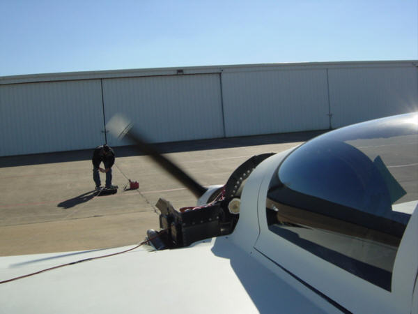
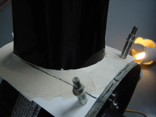
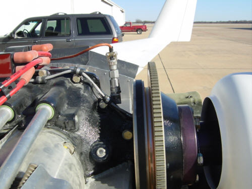
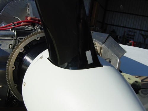
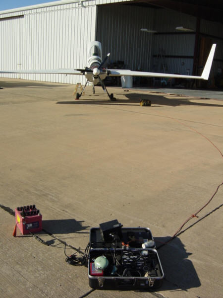
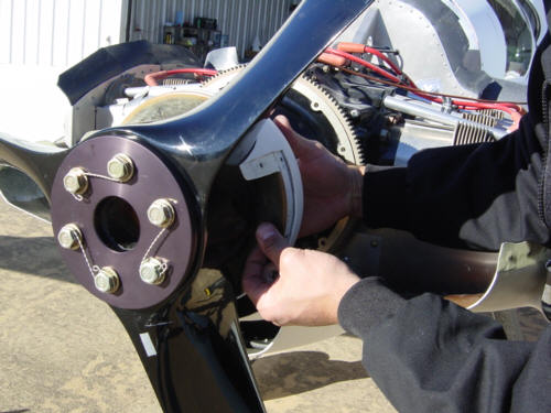
The first step is to attach the harmonic sensor to the engine case so that it is centered and as close to the propeller as possible. A piece of reflective tape is placed on one of the propeller blades - this becomes the reference blade for all the calibrations. The electronic balancer is normally setup in front of the propeller, but as this is a pusher...it is setup way behind the prop. The only minor trick was to make sure the sensor cable remained clear of the prop arc with a little masking tape. My part was really easy, start and warm up the engine, apply fully power and try to blow Pat over. What I didn't capture in the photo is the use of a strobe light which Pat used to "fine tune" and isolate the prop. Combining both the strobe's propeller isolation and the reading from the harmonic sensors, he can determine the amount of out-of-balance (vibration amplitude) and the location on a 360-degree arc (strobe isolation). Remember, dynamic balancing takes into account the internal mass of the engine, the propeller, the airframe AND the spinner - all as one unit. The reference reading was .4 (twice the normal FAA balance limit) - and opposite one of the blades. This is on the "high-normal" end of the scale - Pat said he has seen much worse, but I’d get a noticeable reduction in vibration when he was done. (Yippee!)
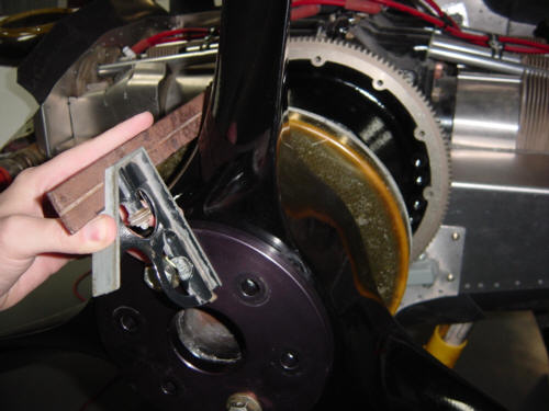
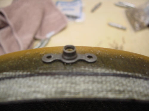
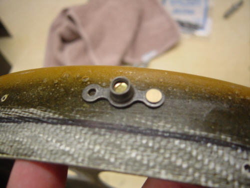
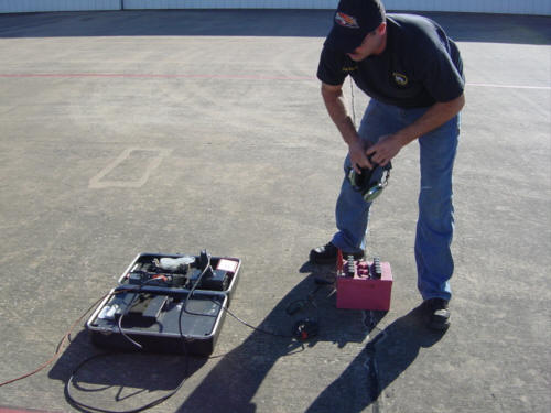
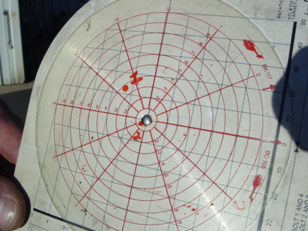
Now the actual balancing took a little longer to work out. It's an iterative process of putting on weight...testing...and re-adjusting. At first, we just attached some weights (AN large washers) to the spinner screws in order to get another data point. We re-tested and determined the weight was just about right, but the placement was a few degrees off. After a few more "tests", the weight was right and the location was determined and now it was time to mount them. We drilled a hole in the spinner bulkhead and mounted the washers with a bolt and lock nut. We put the spinner back on and ran one last trial and...voila!...the reading was now .05 !!! That is 4 times better than the FAA "balance" certification standard. Outstanding! I didn't need the machine to tell me there was an improvement...there was a VERY noticeable change for the better. This picture shows the measurement points from the first and final runs. The new measurement is about as good as it can get and I'm very happy with it. After a logbook entry and a sticker on the prop hub - it was done. Once I got the spinner and cowl back on, the sun was already setting - so I'll have to give it the flight test tomorrow. If the ground runs are any indication, it's going to be a major improvement!
UPDATE 8-26-04: It's almost first flight day, and I still have not installed a spinner. Well, that's OK because you don't need one to fly...just need it to fly more efficiently. A spinner is usually mandatory on forward facing engines as it helps split the incoming air into the two main baffle intakes. On a rear mounted engine, it's completely optional and/or mostly cosmetic. The Berkut kit came with one that was just a stub nose style - nothing wrong with that in itself, but to me it doesn't have the looks befitting this sleek aircraft! It just looks too conventional...and we can't be having that! The new tapered "Hershey Kiss" style spinner was developed specifically for canard aircraft. Aside from it's snarky kewl looks, it does have a few beneficial aerodynamic attributes. It's main job it to help smoothly reconnect the airstreams from above and below the fuselage - reducing drag. As the come together, they also blend more readily giving the propeller a smoother flow that helps reduce cavitations. These effects may be so small, they might not even be measurable with a speed increase. However, the biggest benefit that is measurable most of the time is enhanced engine cooling. The aft cowl opening is increased with the gap around the spinner, and a flow guide (not yet shown) in front of the spinner bulkhead helps re-connect the engine cooling air back into the slipstream more easily. This is usually good for a 10-20 degree decrease in CHT...a good thing for all engines in Texas. In all, the best part is still the 15+kts. of increased "ramp" speed you get from something this kewl looking! (for those newbies, and yes, I've been asked - "ramp speed" = speed sitting still on the ground via sleek and sexy looks alone)
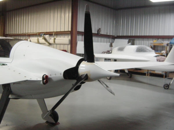
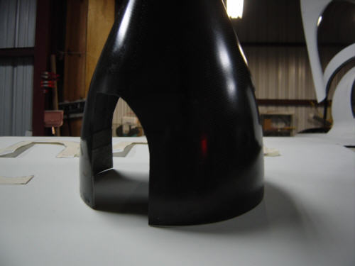
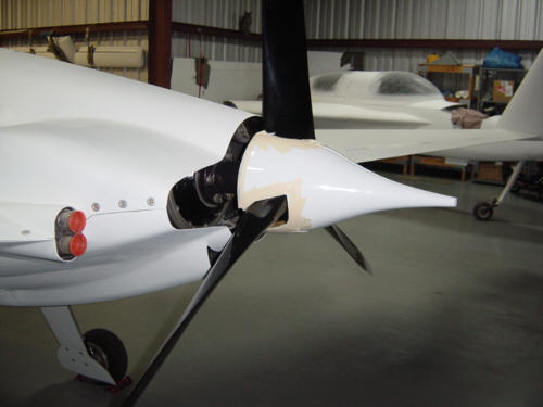
Scott Carter (here he is again, helping me out - WHAT A GREAT GUY!) loaned me a old spinner similar to the one I will be installing. It's already setup for a 3-blade Catto prop and fits nicely on my installation. It may not look like much, but this will save me HOURS of construction time since the holes are already basically in the right place. With some minior tweeks, I can make a template from this one to cut the holes correctly on the real one. Of course, right now this is still a mock-up installation with the template spinner, but can get an idea of how good this is going to look when finished!
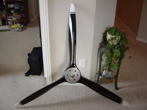
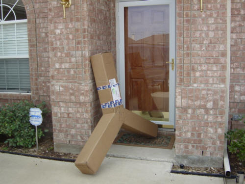
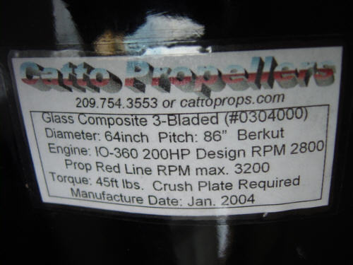
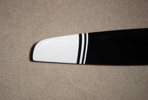
You really know it's a good day when you come home from work and find this sitting on your doorstep! I ordered this thing back in October 2002, but if it flies as good as it looks - it will be worth the wait. For those who are wondering, here are the specifications that are listed on the prop's hub. It's even got snarky looking white crescent tips and pin stripes. A true work of art in my book! You can find more information about Craig Catto's props on their web site: www.cattoprops.com.
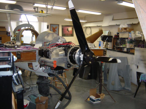
And, yes...I did put it on the plane for a quick peek!!!
OK, I know the debate out there - 2-blade or 3-blade...I chose the later for the following reasons. First, the Long-EZ crowd with O-320's installed have almost exclusively gone to the three blade prop designs. The reasons given: 1.) smoother cruise and less vibration due to a lessened harmonic tendency, 2.) quieter than the 2-blade due to lower relative tip speeds, 3.) better take off performance compared to a cruse prop profile, 4.) better ground clearance - shorter blades for rated engine, and very importantly 5.) sex appeal. The technical drawbacks: 1.) more blades = more drag as a little hp goes away to prop friction, 2.) a few less knots of max cruise - due to drag of course. In simple terms...a perfect prop would be a single big blade but as the Germans found out during WWII, it just was not practical. 2-blades yield the highest practical performance for given power (efficiency) in our engine categories. 3-blade props (may) introduce additional benefits not directly related to cruise performance but with penalty to ultimate efficiency
As I learned long ago with the Mustang...a performance tweaked vehicle is not always the most comfortable and reliable daily driver. It's all about calculated compromise. ;-) Obviously, there is technical merit to both prop choices, and I have made mine...as least for the FIRST propeller going on the Berkut.
 Back to the Proto-page