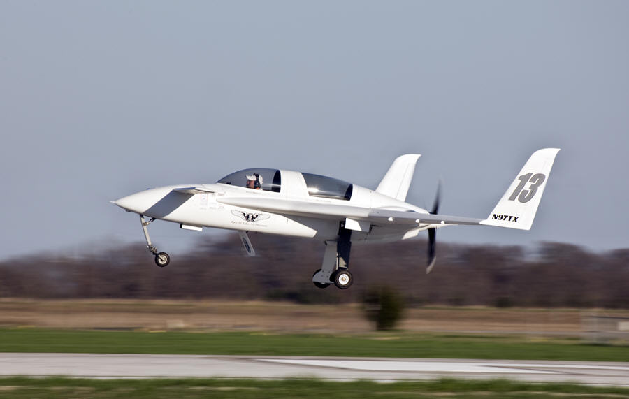
Let me first say that the Sport Air Racing League, and the competition it brings, was the driving force behind my desire to undertake these mods. I am very thankful to Mike Thompson (SARL Chairman), Eric Whyte (AirVenture Cup Race Chairman) and the many other race coordinators and sponsors for helping foster a "competitive environment" that energizes our aviation community to make their birds more efficient and by result - faster. We may never reach Aerodynamic Perfection, but at least we are continuing to evolve. Thanks again, and keep up the great work!
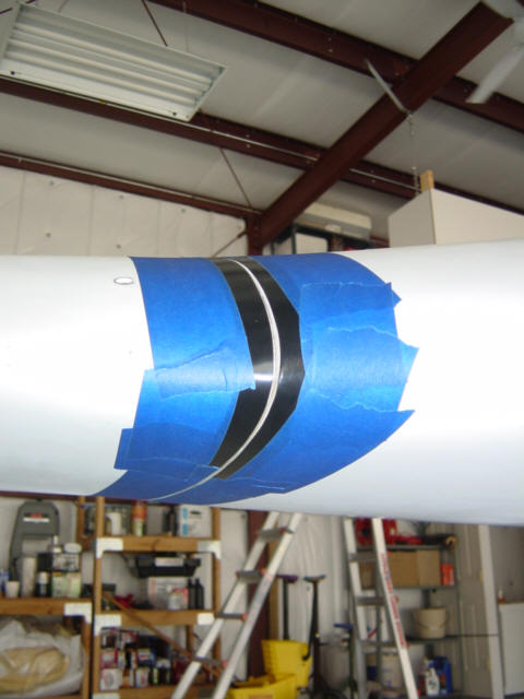
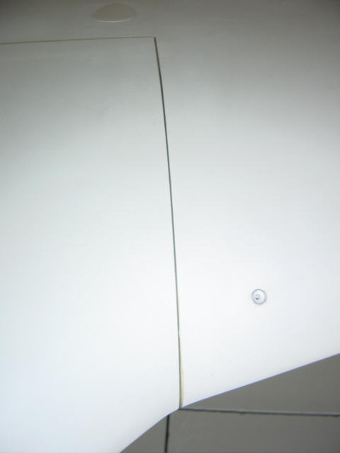
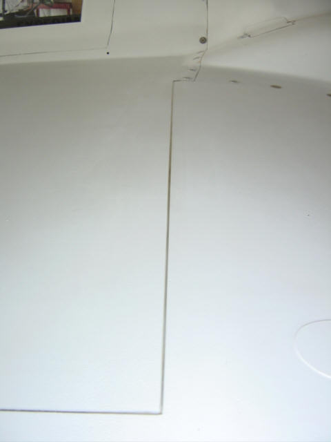
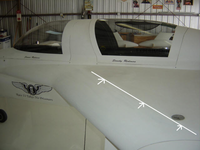
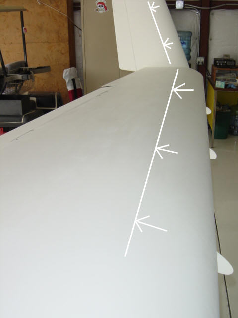
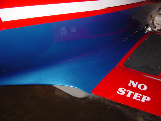
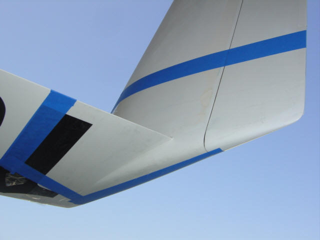
Wing/Strake Intersection Fill: (4-29-07) I'm done with tape! You've heard my bad experience with using Vinyl tape on these intersection gaps right before the AirVenture Cup Race last year - what gained me a few knots for the first 15mins, ended up costing me 5kts. over the rest of the race! Grrr. Well, in preparation for some upcoming races this year, I cleaned up the skins bordering the gaps and installed some brand new 1.5" wide 3M vinyl tape across the gaps. This time, I tested it. It was all great until I pass through 200kts...then, the tape began to lift up from the center and peel away again. It did the same thing that it did during the race - separated in the middle and flopped around like a speed brake on the top of the wings. OK...this is not going to work!
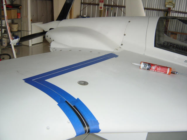
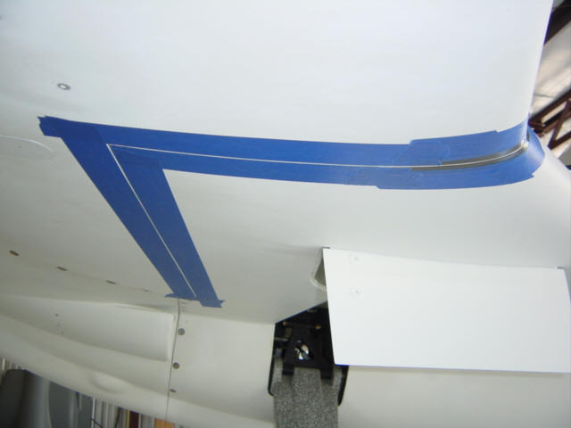
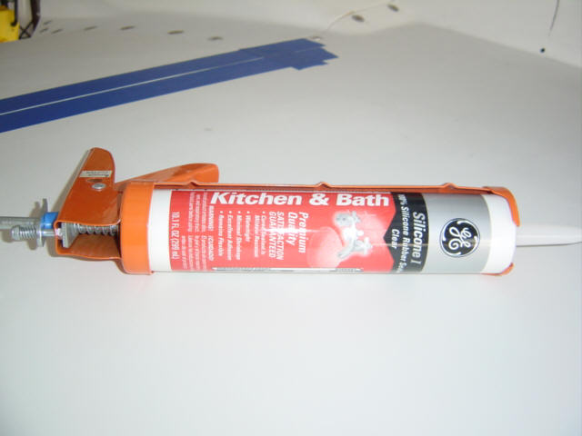
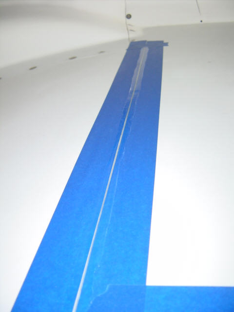
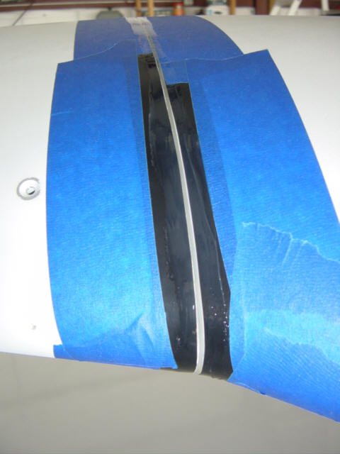
So, I broke down and performed a more robust fix. I started by masking off the borders of the gaps with blue painter's tape on top and bottom, and used black electrical tape for the difficult bends around the leading edge. I had a tube of Silicone Ruber Sealer left over from sealing up the hangar so I loaded it up in the gun and off I went. I shot a bead down into the gaps then used my finger to smooth out the excess and force it further into the gap. I let this tack up just a little bit, then removed the tapes. The result was perfect! I now had a clear and smooth bead bridging the gaps all the way around the intersection. I don't plan to do any flying for the next several days, so there will be plenty of time for the silicone to setup. Finally, I think I have a fix for these aerodynamically dirty areas! Perhaps a race-speed MPH or two is in my future too. ;-)
Status: Complete.
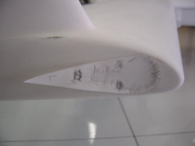
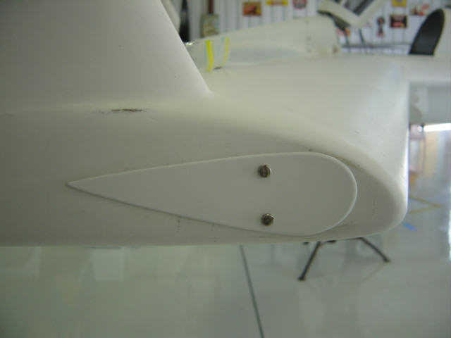
Nav/Strobe Hole Cover: (5-10-07) Here's an easy one. I was in drag reduction mode and noticed how big and bulky (and draggy) the NAV/Strobe light heads were. In race mode, I'm a day VFR only airplane anyway...so who needs lights! I pulled them off and constructed some covers. I made some quick paper templates of the hole area and screw positions. Grabbed some scrap .020" aluminum and cut out a teardrop shaped cover and attached it with the screws and bathtub calk to seal it. Done. There's a little more speed right there!
Status: Complete.
This section is obsolete - see C.R.A.M. section below)
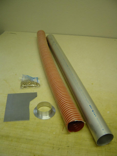
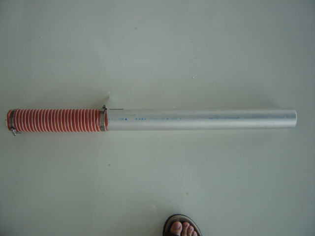
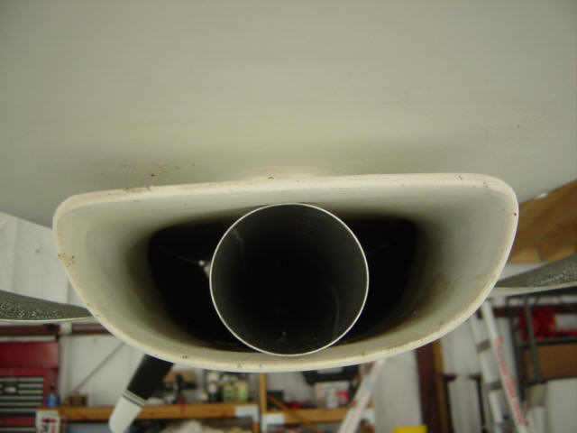
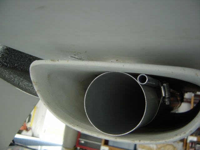
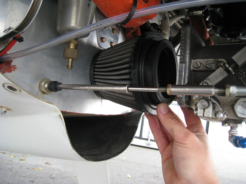
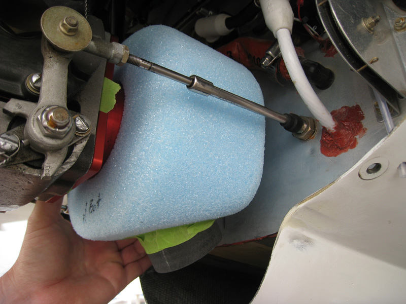
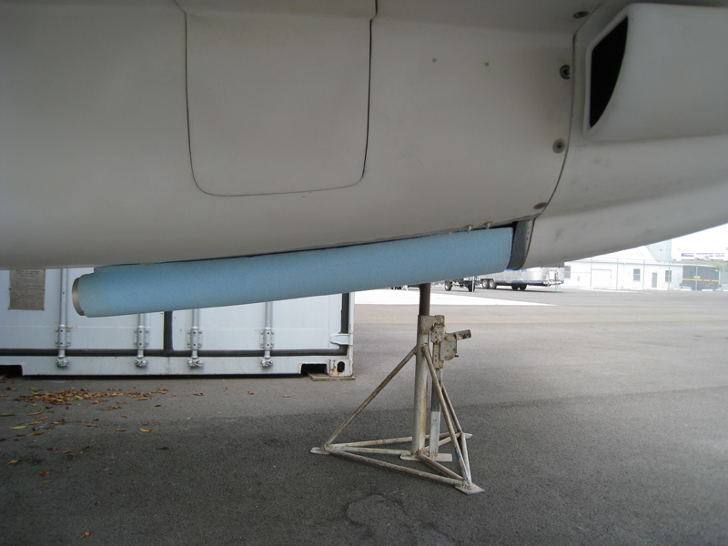
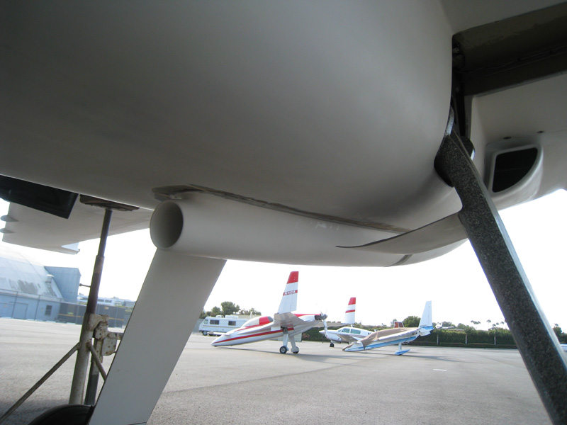
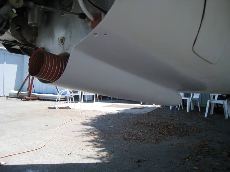
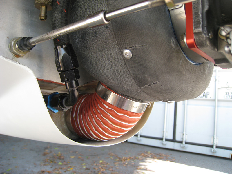
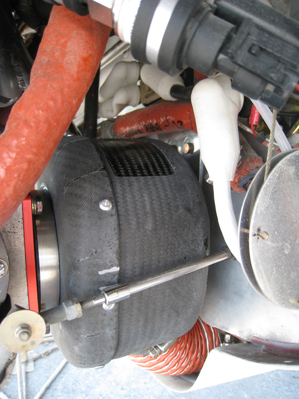
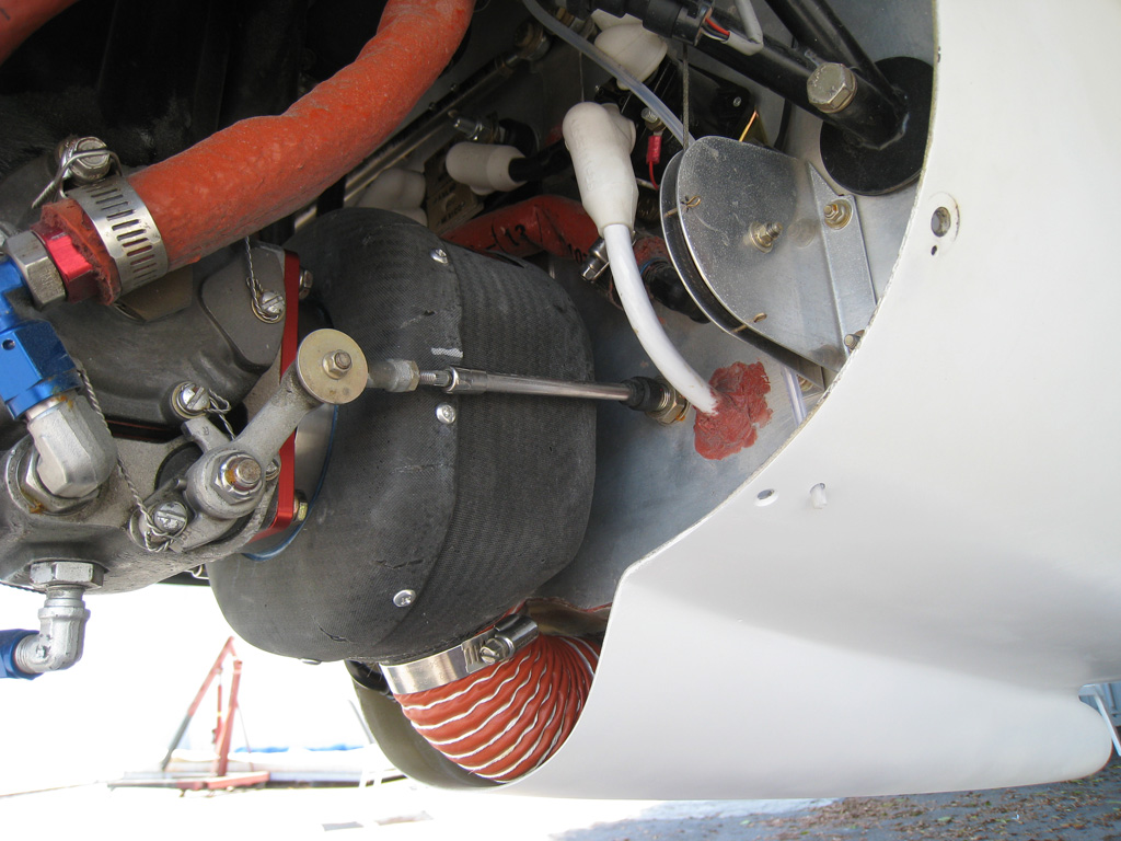
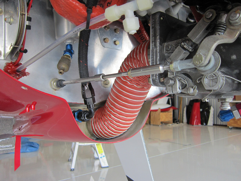
Ram-Air Snorkel for the Engine: (5-20-07) It's Air Racing season again, it's time to do a long awaited speed mod - Ram Air! The K&N filter is pretty efficient, and I know that the lower cowl is being slightly pressurized with the cooling air from the scoops - but I need more. Besides, all the other race planes swear by it. I didn't know if this was going to work, so I wanted to make the first version cheap and easy to build...I needed a working proof of concept before going back and spending a lot of time on it. So, what I came up with was a simple, no-filter, snorkel. It consists of an 2.5" aluminum tube that runs down the center of the belly scoop and uses a piece of SCAT hose to connect it to the fuel servo. Simple, huh.
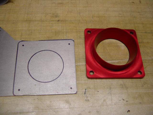
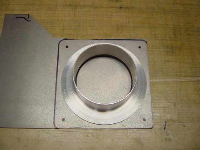
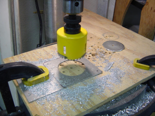
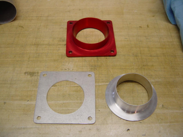
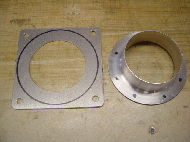
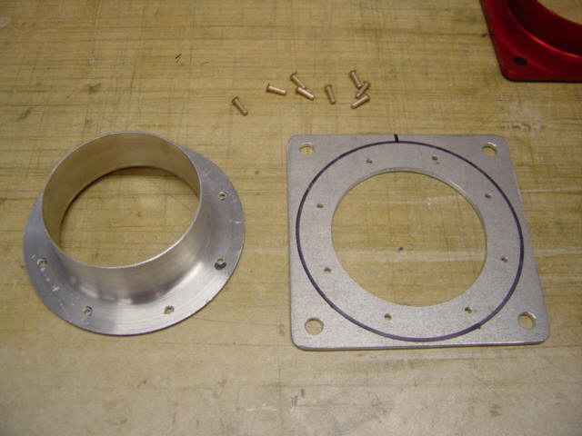
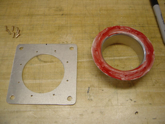
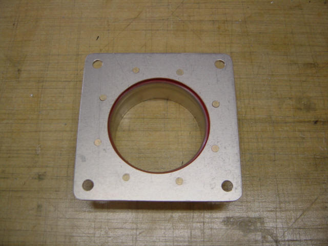
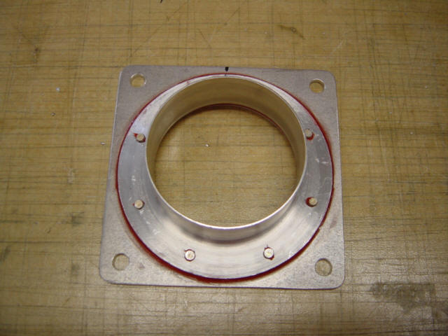
So, I started with some raw materials. I took the old servo flange off and used it to trace the dimensions on a sheet of aluminum. Then I used an aluminum duct flange, and traced the center opening. A hole saw made quick work of boring the hole. I drilled the other bolt holes and soon I had all my flange parts. I marked the new flange for rivets and drilled those holes too. To seal it all up, I used some high-temp RTV silicone and squeezed the rivets flush. The final part looks very good.
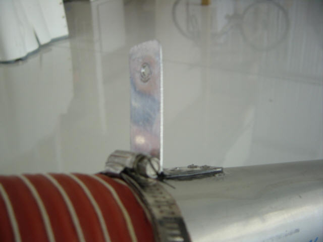
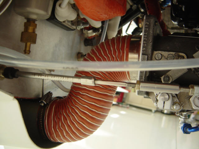
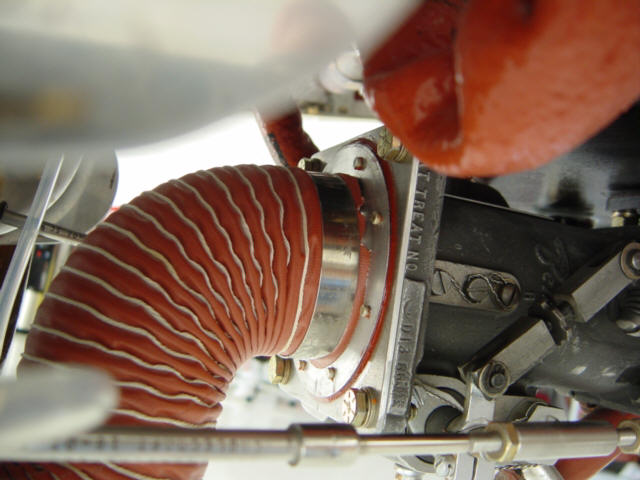
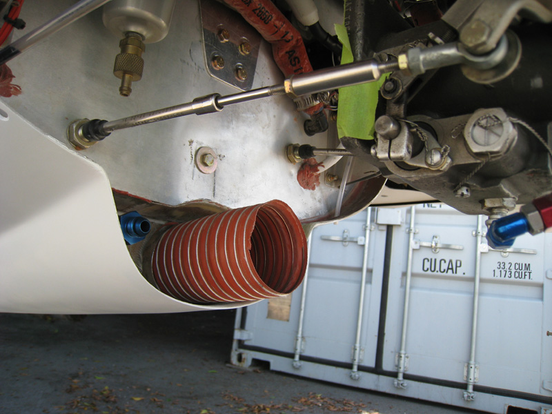
I then cut the 2.5" diameter aluminum tube to fit the belly scoop, and installed a bracket to hole the tube in place with a bolt into the firewall. I attached a short run of SCAT tube to the tube and installed it into the center belly scoop. The SCAT tube snakes up to the servo flange and is held in place with hose clamps. Simple...and it works.
Tests flights show that the "snorkel" only, is good for a .4" to .5" increase in manifold pressure which roughly translates into 40-50 additional RPM. This is a good start, and proves I can get increased pressure from this location but I will need to add a plenum for air expansion to take full advantage of what ram air has to offer. I could see as much as a 1.5" increase with the addition of a working plenum. But that will have to wait for version 2. Cooling: No change to cooling at all. The arm pit scoops are the primary for cyl cooling and those remain un-affected. The belly scoop is mainly for the oil cooler and that NEVER gets above 184 degrees anyway...so there is really too much center scoop to begin with. I actually have a problem keeping oil warm and often use a blocking plate. The only current "problem" (not too bad of one) is that the mixture distribution is screwed up due to the differential pressures between the intake and the injectors. It's still on the rich side of peak, but I may need to add injector shrouds and plumb them into the same plenum that the intake air gets to get more equalized EGTs. More experimentation is needed in this area, and I certainly won't do this until I have a working plenum installed.
Status: Version 1.0 Complete.
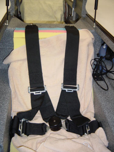
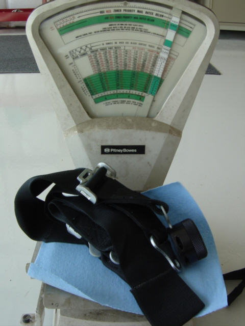
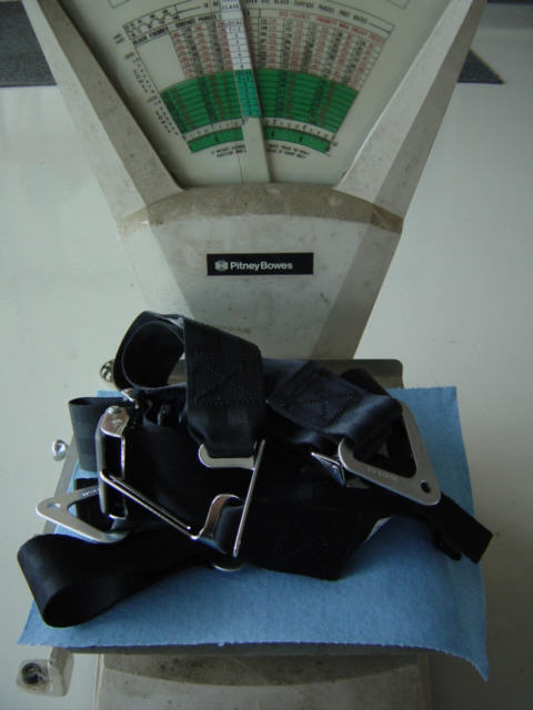
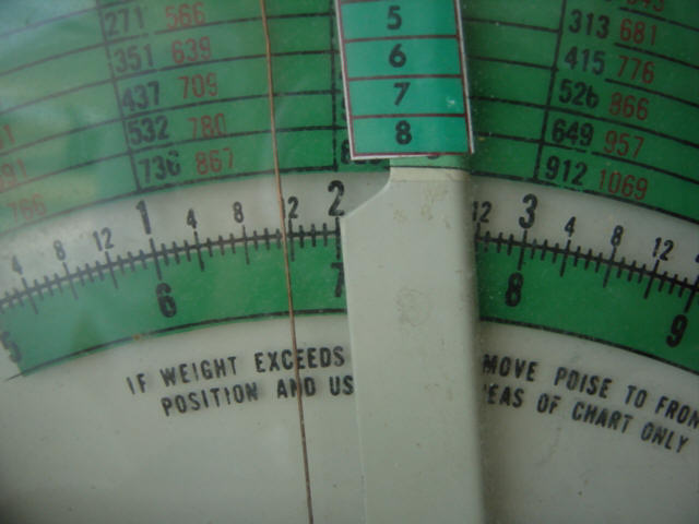
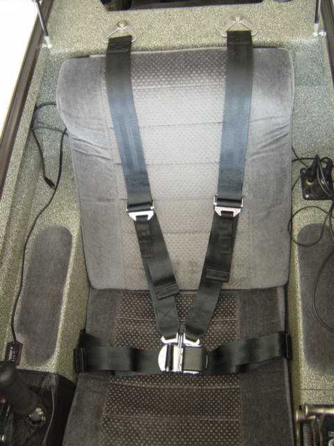
Replacing the seat belts for a 5lb weight reduction: (6-15-07) It was time to order the seat belts for Scott Charlton's Berkut so we were looking through the catalogs to see what was available. Scott decided to try the seat belts available through Aircraft Spruce that were designed for the Long-EZ. I had originally avoided those as the older versions only adjusted on one side of the lap belt, meaning that the shoulder straps would skew to one side when adjusted for a small person. I didn't want that, so I went with belts that were designed for race cars - very heavy duty. They sure did the job, but were big and bulky...and VERY heavy. When the new belts arrived, I noticed they were very lite and adjusted on BOTH sides of the lap belt. Hey! This was a major improvement! So, before they could be installed in Scott's plane, I took them out to the hangar and tried them out. ;-)
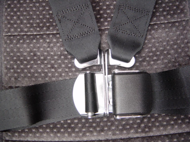
I first pulled the old front belt out and weighed it. It can out to be a whopping 4+lbs for the one belt. Then I weighed the new belt set and it came up to be a scant 1lb. 11.5 oz.!!! WOW!! I quickly installed the front seat set and tried them on for size. The fit like a glove, and the straps are more easily adjusted and can provide a much tighter fit as well. The latch on these is a little different but mostly like the standard latch in an airliner. In short, I like them! So, these are staying in my Berkut...Scott will just have to order a new set for himself. ;-)
Update 6-18-07: I guess you guys really like those belts (as do I) since several folks have asked for the ACS part number for them. Well, click here and it will take you straight to them. Enjoy. PS - Please note the ACS part number: 13-01300 Fitting, no?
Status: Complete.
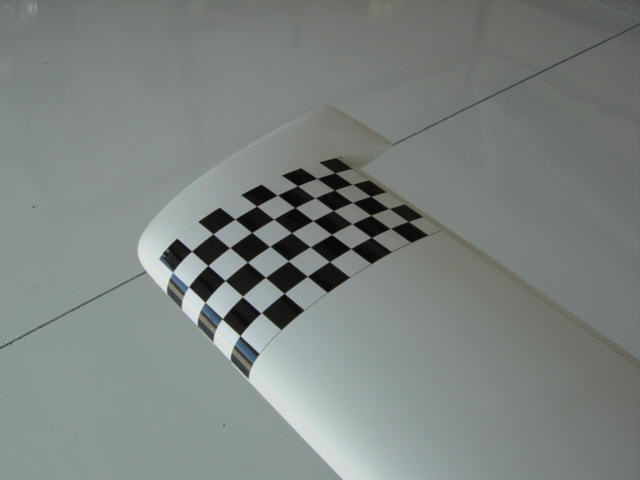
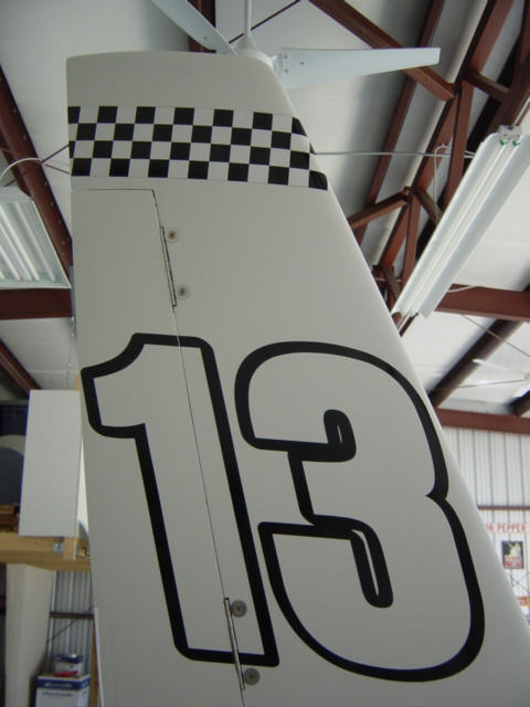
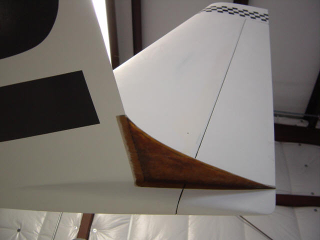
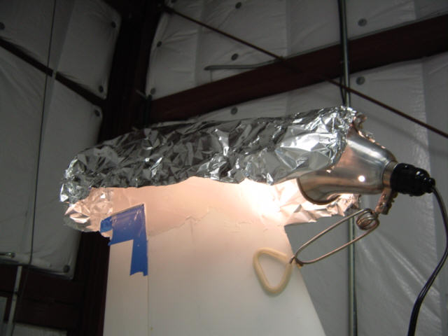
Smoothing out the High Pressure Areas: (6-15-07) If you have seen my plane in person, you know that I have yet to put sandpaper to the upper surfaces after rollering on UV-Smooth Prime. Well...at least the fuselage...I did couture the wings and canard, but not to the point of "ready for paint". I did surface the belly and bottom surfaces, as the plane needed to be up-side down for that...but left the top raw as that side experiences the most wear-n-tear. This didn�t seem to be slowing me down any, so I really didn't worry about it until I flew my luggage pods right after applying the primer. I rollered it on, just like on the fuselage. I had flown the pods naked a few days before and the performance was what I expected and they flew well. After the rough primer, they flew like I had added two anchors to the wings! Amazing difference! This got me thinking...the pods are almost 100% high pressure frontal area (wetted area). If they were experiencing high drag, then the rough primer, high pressure airframe areas were too! So, in my quest for more knots, I got the sanding blocks out and started cutting it all down. I still wanted to keep the rugged exterior until I was really ready for paint, so I only sanded the high pressure zones - Strakes, Wings and Winglets. The cosmetics (as it were) took a hit as now I have high spots showing through and a modeled, multi-shade white finish. (sigh) This is what I have to put up with until I get this damn thing painted! In the mean time, I found some black and white checkered vinyl tape on the Internet. So, I went to work putting some race accents on the canard and winglet tips. Hey, I got my $8 worth!
Status: Complete, but not yet tested for speed.
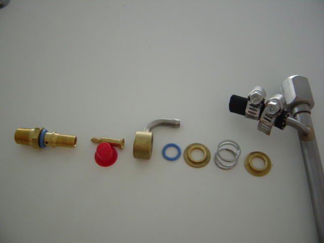
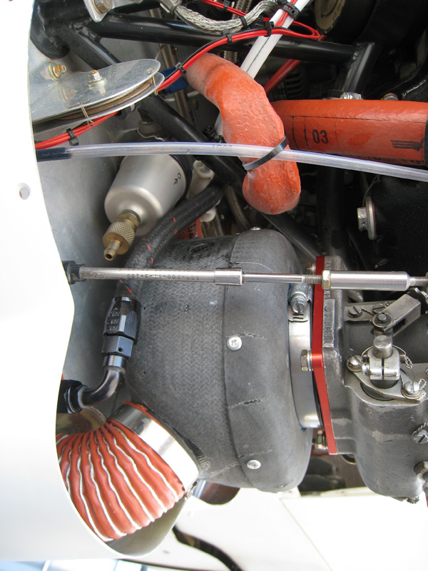
Turbo Injector Shrouds and Bleed Air System: (10-2-07) No, I'm not super or turbo charging the Berkut...but I do need some of that technology for racing and Lean of Peak operations. You see, since I installed the ram air snorkel, the engine runs much leaner than it used to at race speeds - causing the operating temps to rise. And during normal cruise, I couldn't lean my engine out as much as I would like to without it getting very very rough. After asking around and a great conversation with the folks at AirFlow Performance, it was determined that the fuel injectors were suffering from an air pressure imbalance. All fuel injectors used on these engines have a small port exposed to the air pressure that surrounds the injector. This air is used to combine with the fuel to form a spray and needs to be at or close to the same pressure as the air going into the servo. In my case, this air (at the injectors) is at the same pressure as the lower cowl because my injectors are mounted to the primer ports on the bottom of the cylinder. This was fine when the air filter was mounted in the same pressure area. But when I added ram-air...it caused an imbalance. In addition, my past leaning troubles were likely cause by turbulence inside the cowl at the high speeds that the Berkut flies. So...what's the fix? Simple...install turbo-style injector/shrouds and a common reference pressure system.
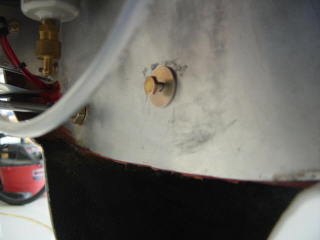
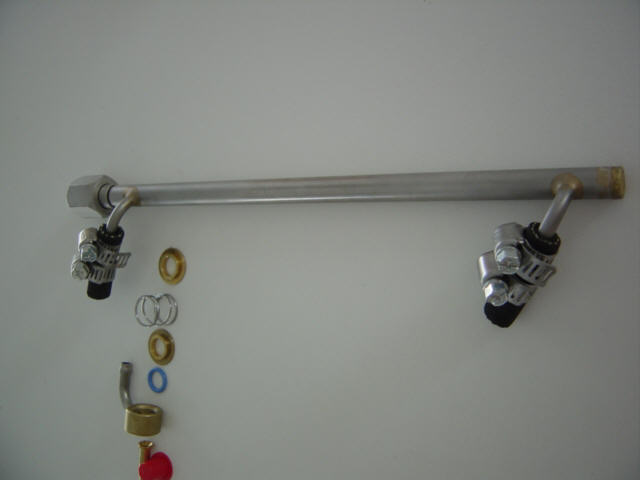
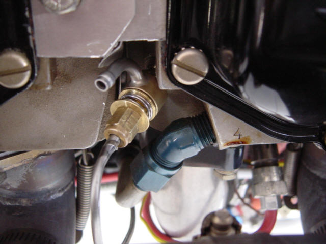
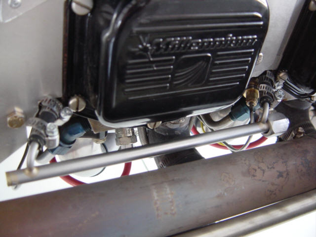
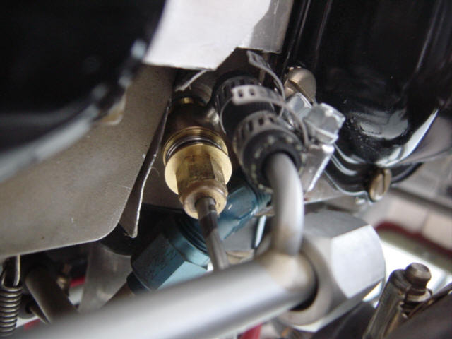
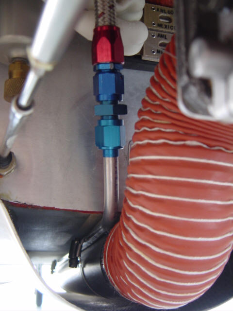
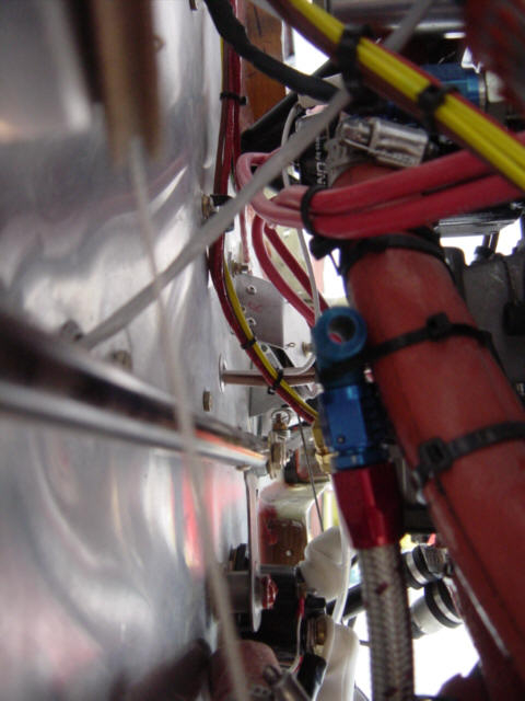
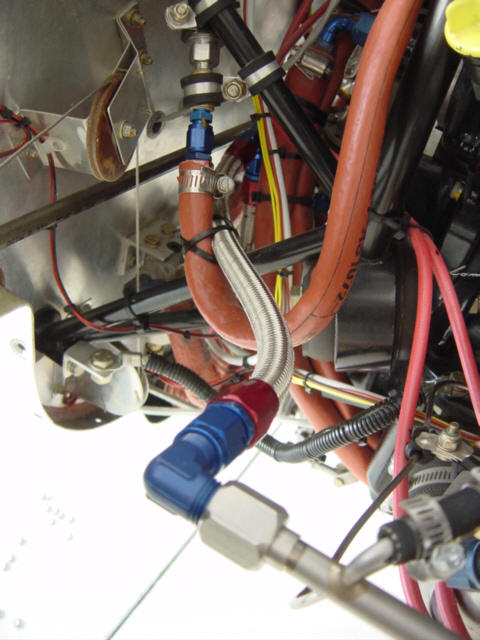
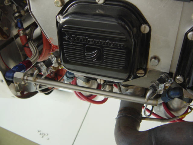
I ordered up the parts from AirFlow Performance and got to work. The new injector assembly has many parts - the injector (note the small air hole), fuel restrictor, shroud, O-rings, capture plates and spring. The shrouds connect to air rails that supply the "common" pressure air. When the injector and all the parts are installed on the cylinder it looks something like this. You can see the snorkel on the shroud that connects to the air rail with a short run of rubber hose. Now that the injectors are "shrouded", I needed to connect them to the same pressure air as the servo. I did this by running a 3/8" tube along side of the large ram-air snorkel so it terminated at the front of the belly scoop. It clamps on and runs aft into the lower cowl area, connects to a flex hose that runs up and terminates into a T fitting. From there, more flex hose runs to the two injector rails on either side of the engine. Here is the final assembly.
I've run some tests and so far so good. In can now run race speeds AND richen the mixture to cool the engine. I also noticed that the EGTs are much closer together and at cruise speeds I can lean the engine all the way back until it quits without it running really rough and coughing. In the coming flights, I'll do more testing but it looks like all the issues with the mixture are solved.
Status: Complete.
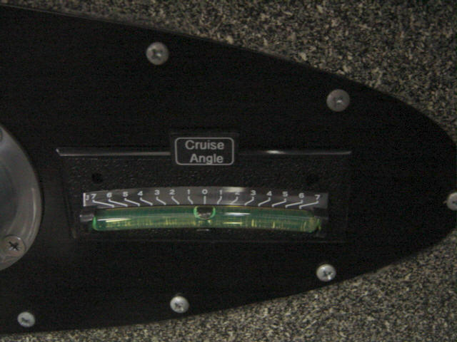
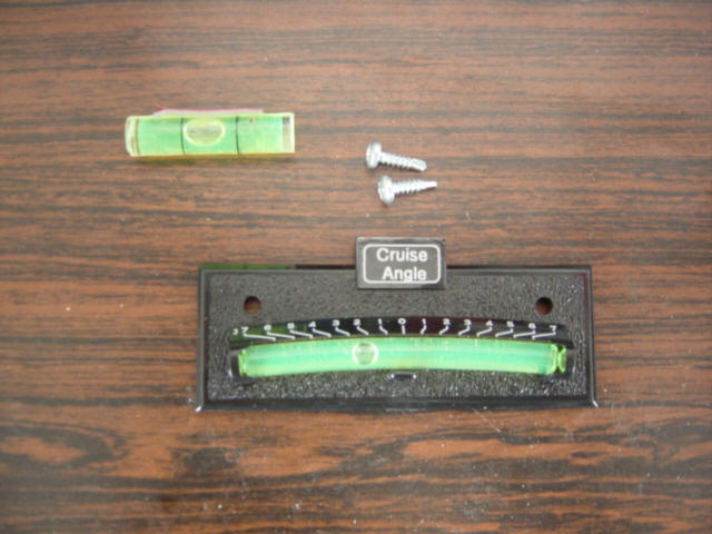
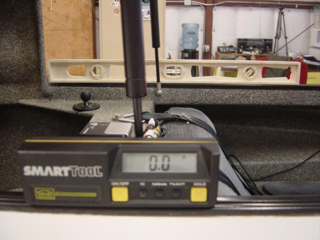
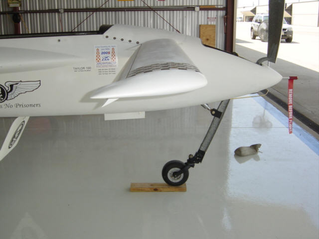
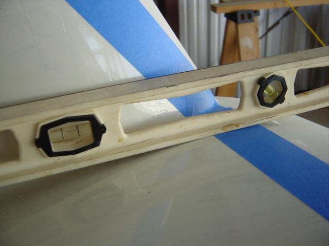
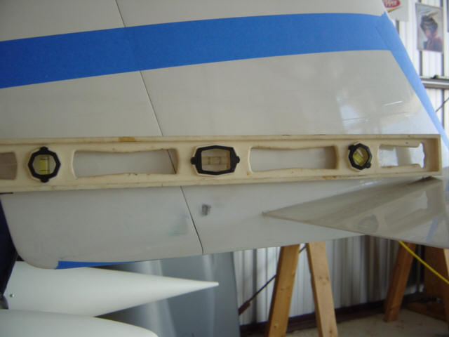
Cruise Angle Indicator: (3-12-08) OK, actually this is an old mod...I'm just a little late posting it one the site. I've been working on and researching/contemplating several aerodynamic modifications to the Berkut. All of which will help optimize it for cross country air racing - SARL style. So, it is important to know exactly that the airfoils, airframe, and control surfaces are all doing. One of the most basic, and most important variables to define is "max cruise airframe angle". This is the angle of attack at which the airframe and fixed flight surfaces travel through the air...in this case, at max speed. So, I came up with this - a Cruise Angle Indicator. I initially tried a standard bubble level but it really work well. The final version is just a parking angle indicator for a camper trailer or RV made by "Hoppy". To install it, I just leveled the fuselage using a Smart Level and carefully installed the indicator at "0". You might ask - "Why not just use a smart level in flight?" Well, I did try that. The Smart Level was WAY to sensitive and jumped around wildly. The bubble in the arched glass tube is naturally damped and is just as accurate. Hey, it's simple, easy and it works.
Status: Complete.
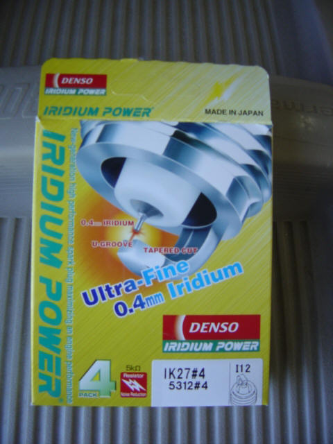
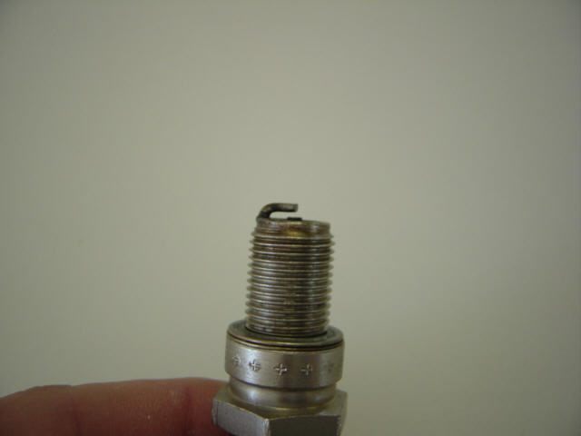
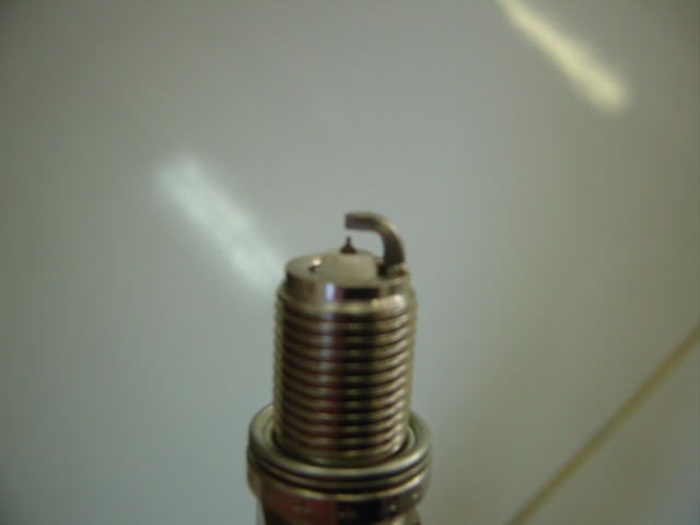
Iridium Spark Plugs: (3-16-08) Well, this may or may not really be a "performance mod", but it's close. The main reason I switched to Iridium plugs was to get a longer, more accurate service life. The electronic ignition seems to wear down the electrode of normal plugs quite quickly (50 hours) requiring frequent re-gapping or replacement. The Iridium plugs have a much smaller electrode made of Iridium that is good for 2500 degrees Celsius! That means it shoudn't erode like the others. It also has a projected nose that puts it further into the combustion chamber and is clocked to face the center fo the chamber. That is the "performance" side - a hotter spark kernel, more consistent gap for a more precise flame front and overall burn. They should also be a little harder to foul. All around, a better plug...and they run very smoothly.
Status: Complete.
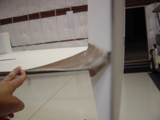
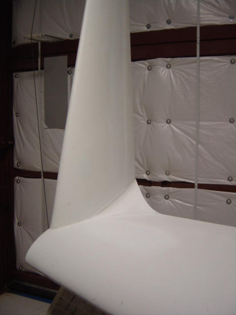
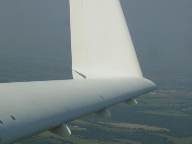
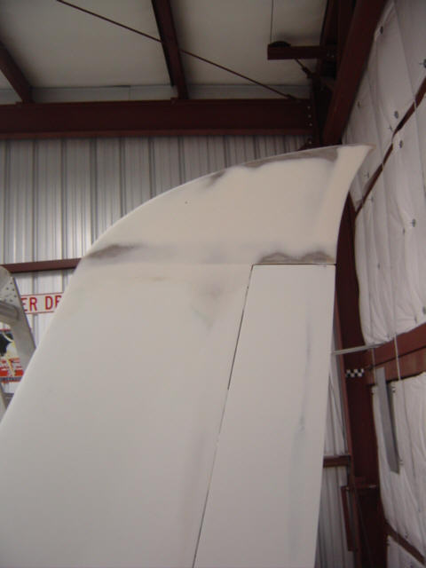
Wing/Winglet Intersection Fairings: (3-18-08) Another late posting, but I'm catching up. You may have already seen this mod in the CSA newsletter but I'm going to go into more detail here. The fact is, this was a big mod to undertake - not the actual build, but the R&D. It took lots of time researching, reading, studying, conferring with experts, and even hunting fairings in the wild. It was WAY worth it and I learned a whole heck of a lot while doing it too...and have a faster airplane to boot. So, lets get on with it...
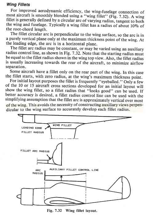
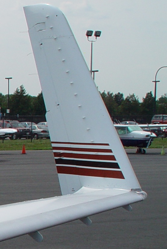
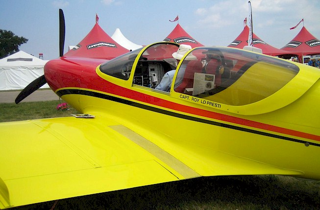
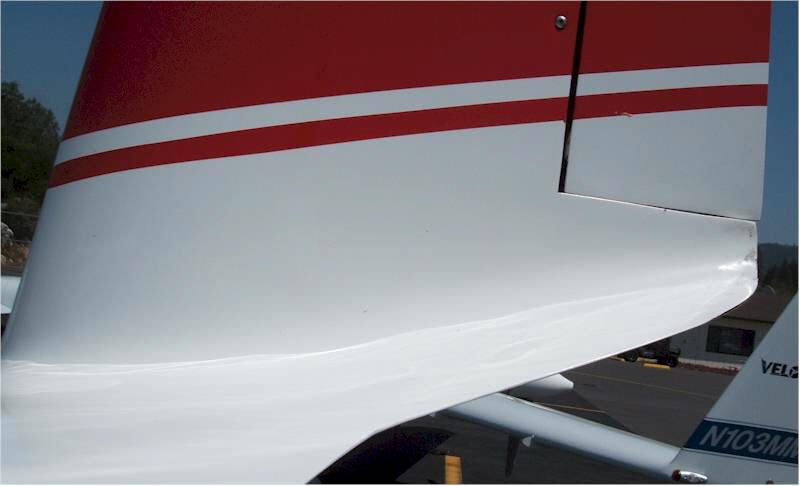
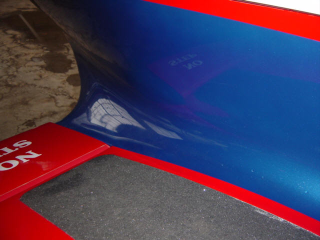
Any change to an aircraft requires research, and lots of it. I first learned about Jack Morrison's experience with blended winglets on his highly modified E-Racer at the AirVenture Cup race into Oshkosh in 2007. It was a whole lot of work but he reported an average speed gain of 10kts from the re-design of the winglet to wing intersection - in this case, blended together as one structure. He had performed detailed speed measurements as well as tuft testing throughout the process to accurately capture a baseline and performance data. (It's the only way to know for sure) So, that's exactly what I planned to do as well!! This set me down the path of collection lots of data. I did numerous on-line searches and found lots of great data - here's one quick primer on a wing intersection fairing - page 1, page 2, page 3, early wing fillet. I also just started looking around at what was alredy out there - business jets, the Starship, LoPresti Fury, Evolution EZ, and especially my main competition - Lancair wing 1, Lancair wing 2. I also ordered a copy of Hoerner's book on Aerodynamic Drag - a GREAT resource! There was so much more, but I won't bore you with the details...lets get flying.
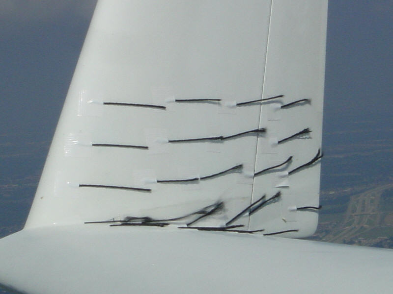
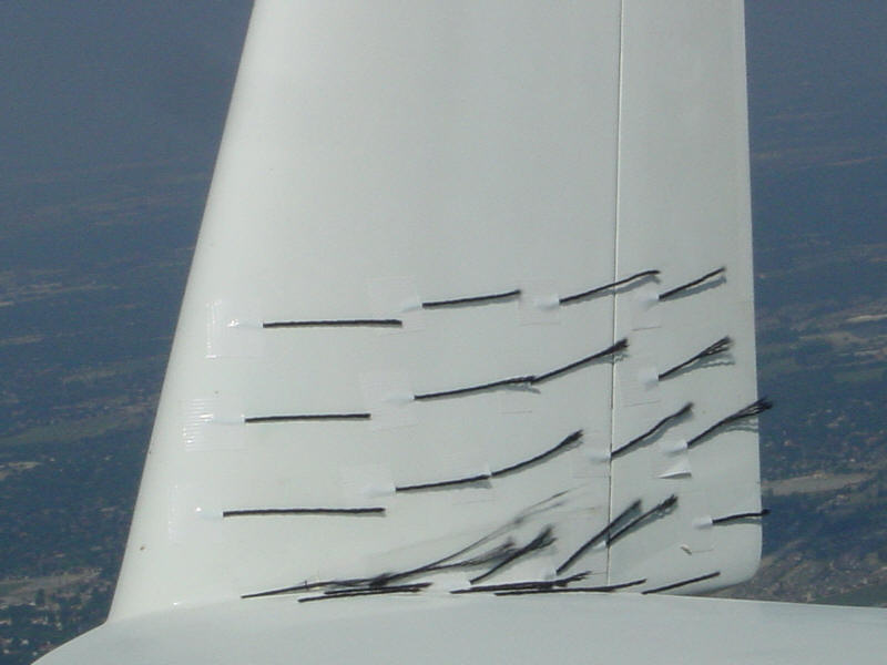
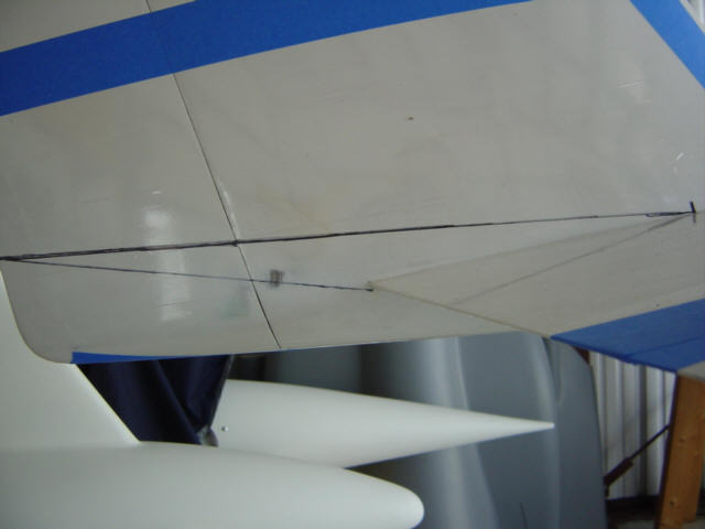
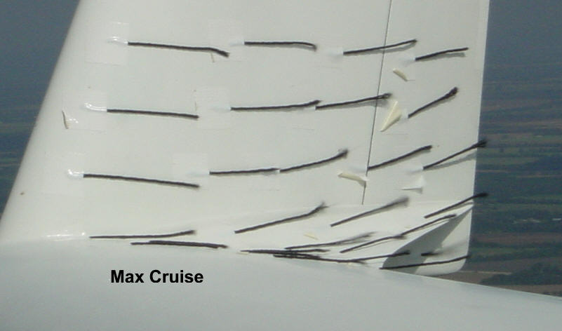
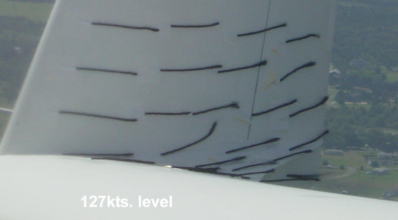
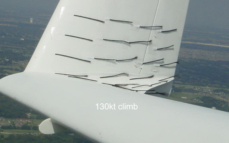
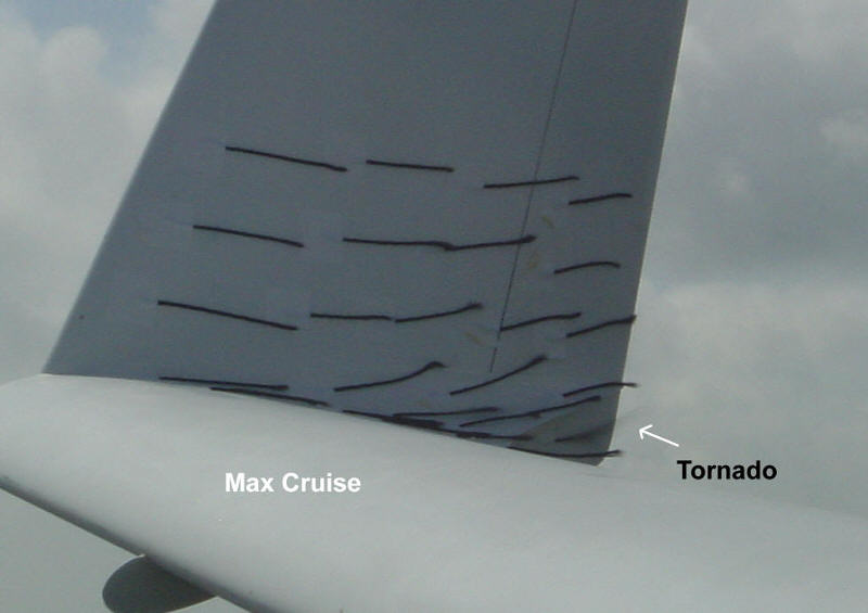
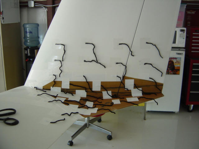
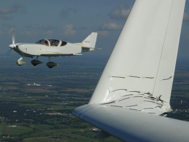
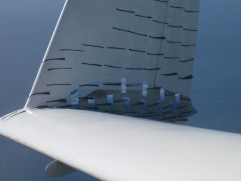
Next up was the baseline speed and tuft tests. I used my same speed testing procedure straight from the National Test Pilot's School website - after noting the atmospheric variables basically fly the 4 cardinal headings at the same density altitude for 1 minute each, record the GPS ground speed for each leg, repeat 4 times and plug the numbers into the provided worksheet and it calculates the wind corrected speed. This provides a repeatable test format allowing a comparison of before and after data. So I made 4 runs and used the average. I then tufted the winglet to see what the airflow on MY intersection was doing. As expected, the air was departing at the intersection in a fan shape and climbing up the winglet. I also shot a movie of it for reference too. Yuck! Well, at least it proves there's room for improvement.
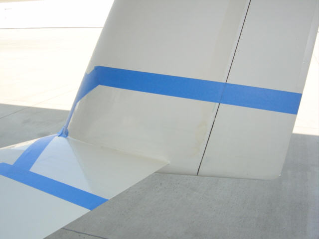
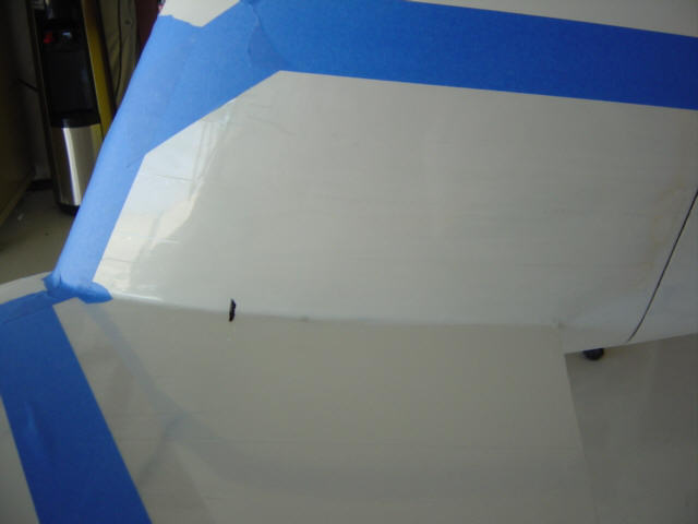
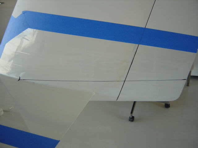
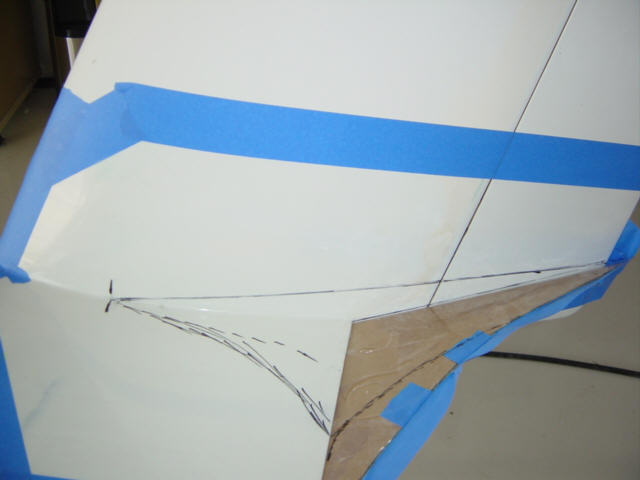
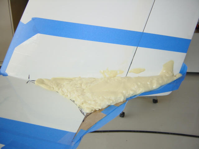
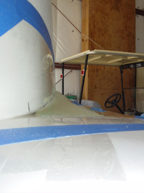
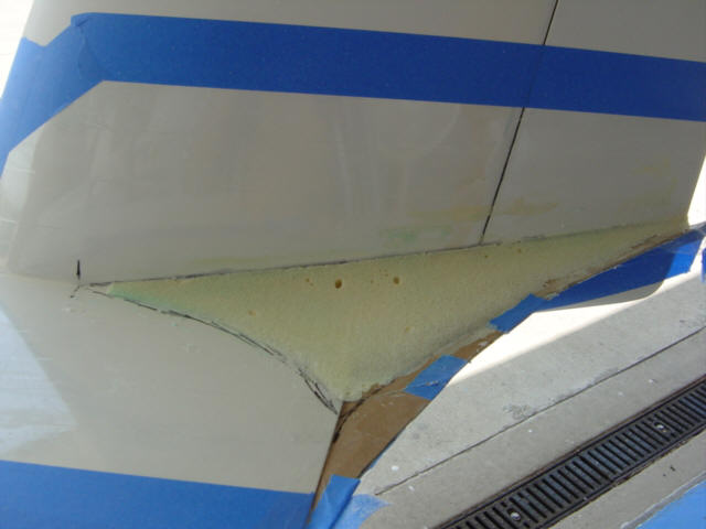
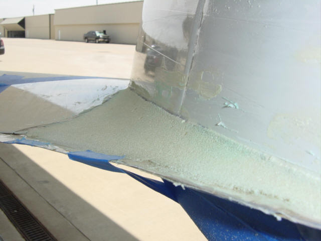
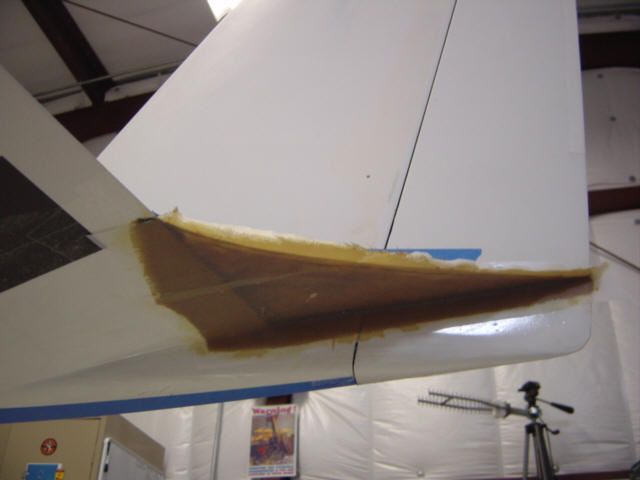
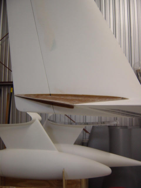
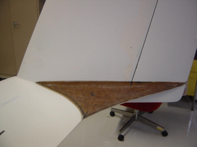
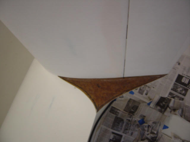
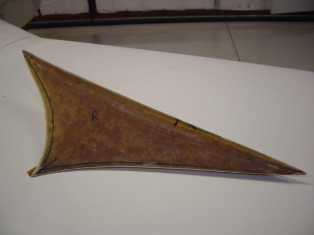
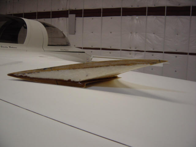
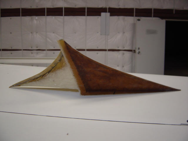
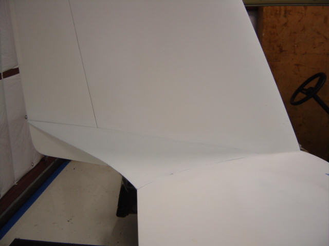
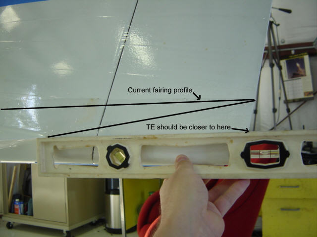
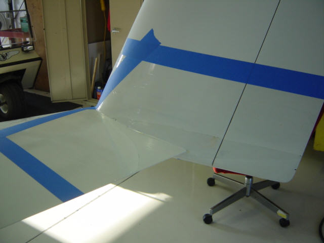
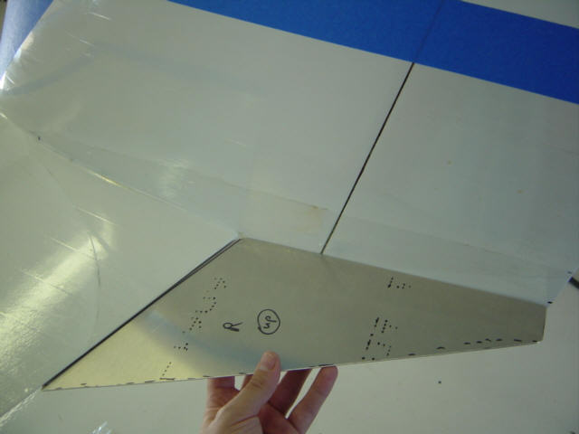
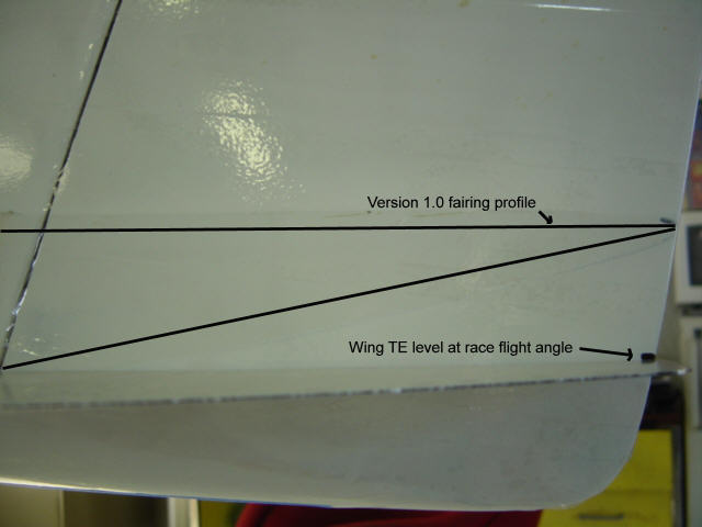
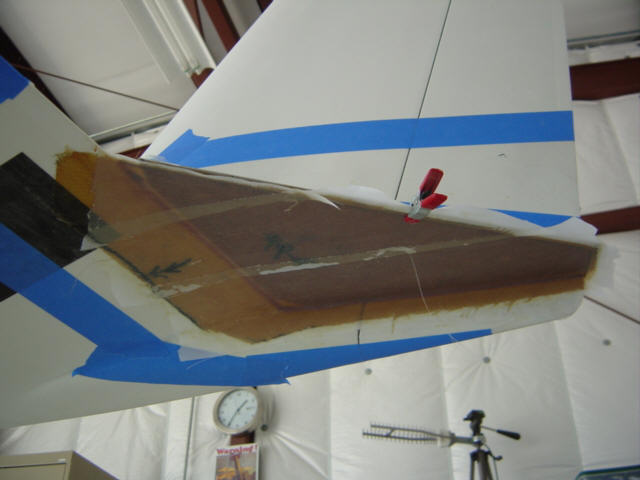
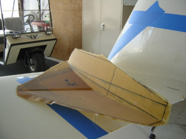
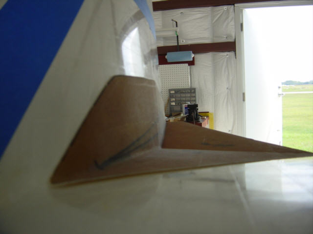
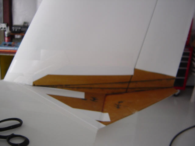
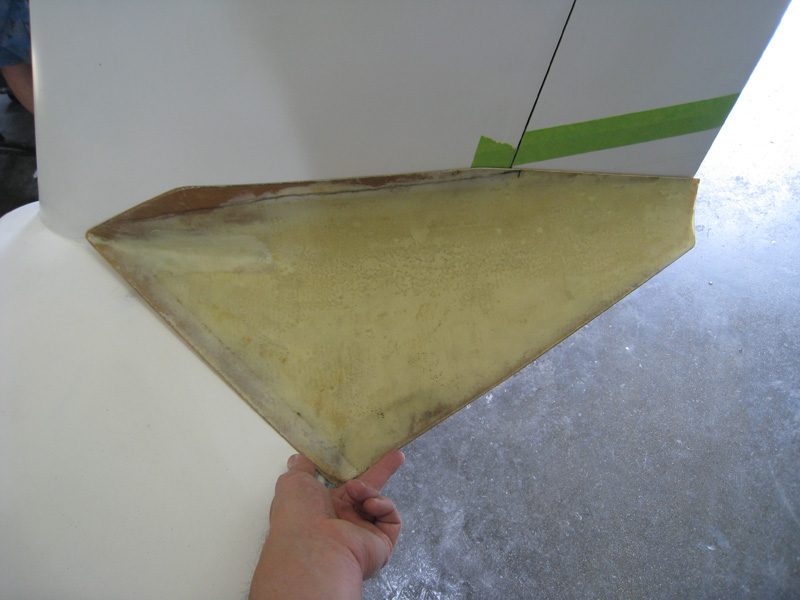
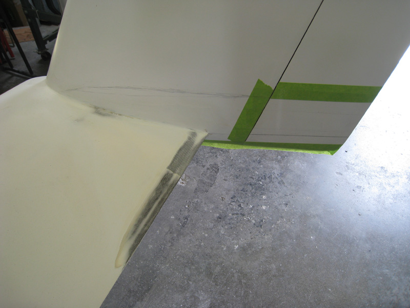
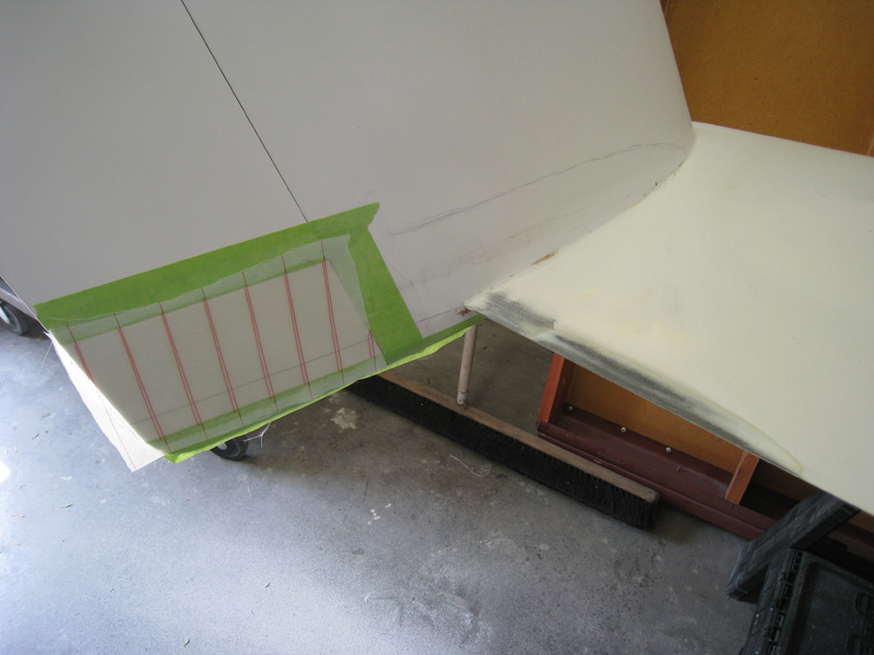
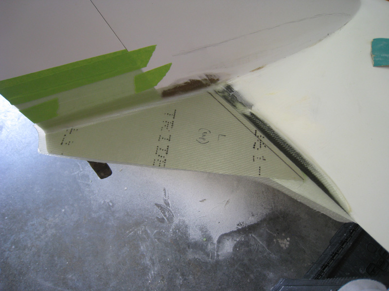
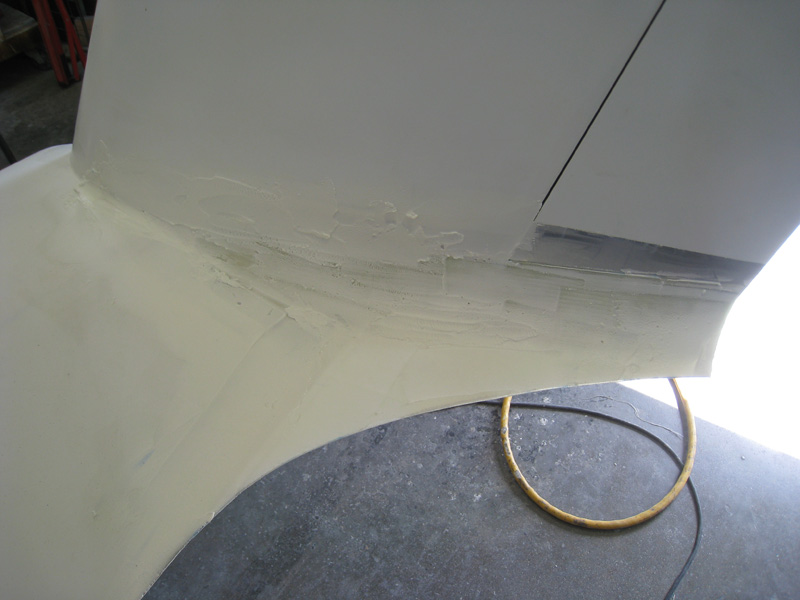
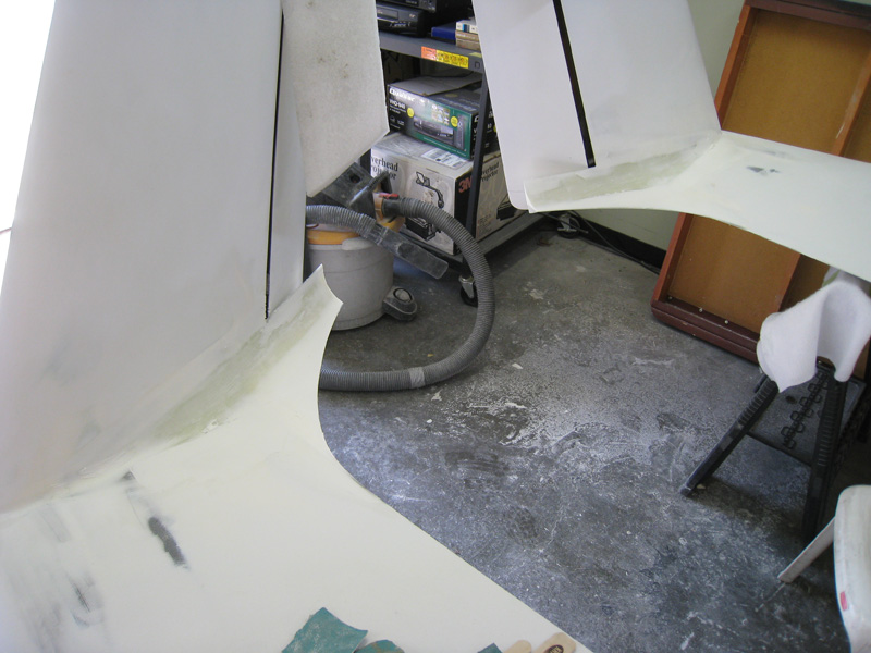
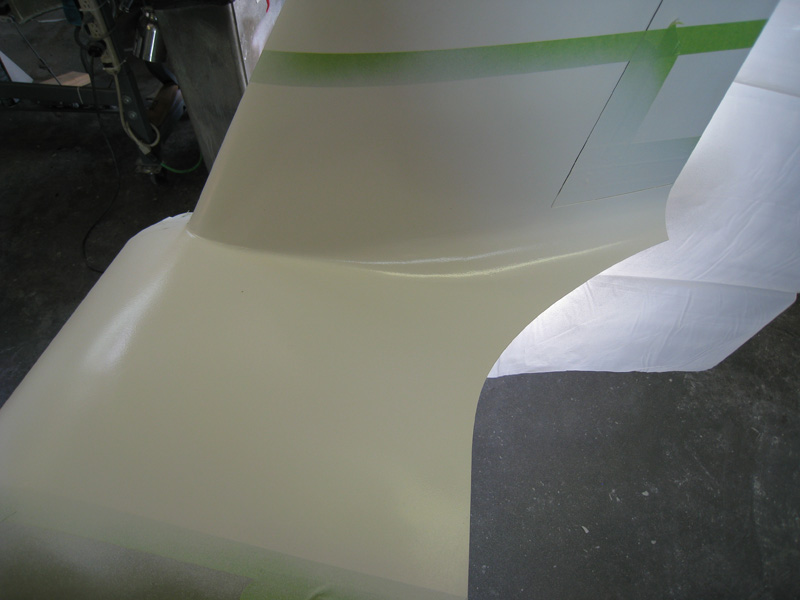
There were a few other canardians that were also experimenting with these fairings, so we were in constant contact comparing notes. I must admit, I skipped a step here and just started building the first version of the fairing as I was running out of time before the next SARL race. I should have created a TE fence only, tested that alone, optimized it, then moved on to the fillet. I got lucky - the version 1.0 fairing worked...but will ultimately need ot be re-built as it is not optimized. More on that later. I started the build by masking off and covering the upper and lower working areas with packing tape. Then I used my handy cruise angle indicator to jig the airframe up at the correct race profile angle. Now that the airframe is at the correct angle, a standard level is used to find the top of the main wing camber. I marked that spot and used the same level to scribe a line from the max camber point to TE of the rudder. (this was the mistake) A second line was then drawn from the wing TE and intersection the other line at the TE of the rudder - this scribes the side profile of the fairing. For the top profile, I simply added a cardboard template to bridge the wing TE to the rudder area and drew in the rough contour lines. With the contour lines as a guide, I poured on the grow foam and let it expand over-size. After a quick cut down and sanding, a rough fillet was taking shape. Here are a couple shots of it from various angles: front view, side view, and rear view. 2-ply of BID glass was added to the upper surface, covered with peel-ply and let to cure. The next day I added 2-plys BID glass to the bottom. Once cured, I popped them off, trimmed and sanded the edges, removed all the mold release tape, and did a trial fit - they look GREAT! A few more shots form various angles: Side view, bottom view, aft view, and looking down from above. Since they are removable, I took some more pics while they were off: top surface, outboard surface, and bottom surface. After a little white primer was added, they were ready to fly - 1, 2, 3, 4. I attached them to the wing on all touching surfaces with RTV silicone. After cure, I took them on a quick test flight and they performed perfectly. Time to get out the tufts!
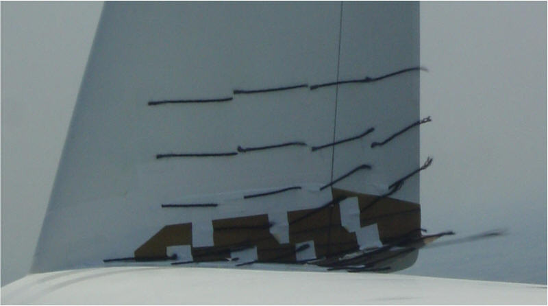
I put all the tufts back on and performed the same flight profile I did previously and the results were fantastic! According to the tufts, the airflow has been significantly improved at max cruise!! In fact, it was also improved at slower speeds, and climbs as well. Anyway, the tufts were much less active (flopping around) and mostly just layed flat against the fillet - which is exactly what I wanted to see! However, it was not all "good news"...remember that mistake I made...here's where I found it. Because the upper fillet line was scribed too high, the air was being tripped on the bottom side of the fairing and causing a small vortex to be created. This equals drag! So, although I have significantly reduced the overall drag of this area, I caused a small amount of new drag to be formed....oops! Version 2.0 will fix this.
Now that I know the fairings were working, I took all the tufts off and did some serious speed and performance testing. As I mentioned above, I waited for a good testing day and flew the same testing profile I had before and compensated for the atmospheric variables - same density altitude, and close to the same temperature/humidity, etc. The plane ran a full 4kts faster the first time, and 5kts faster the second set. Happy with these results, I landed and took one faring off the airplane - this will allow me to measure the amount of drag savings by measuring the amount of asymmetrical drag. With one winglet naked, and the other faired, the slip/skid "ball" was about 2/3 of the way out of coordinated flight requiring rudder input on the faired side...meaning the un-faired side had more drag! These two tests were proof positive that the fairings were doing their job and were actually reducing drag, resulting in the measured speed increase. YEAH!
These finding were also backed up as I closed the gap even further between myself and my main competitor, Larry Henny (Lancair 360, Race 36) and came within 16-seconds from beating him! Sweet! You would think I'd be happy and move on...NO WAY! Testing also showed there was still room for improvement...and that's what's up next.
Status: Version 1.0 Complete - Measured speed gain of 3-4mph, flow not optimum, temporary
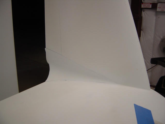
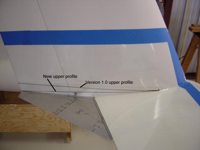
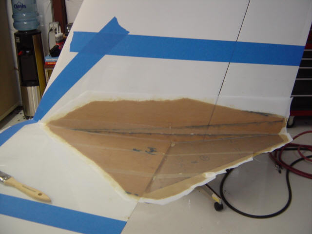
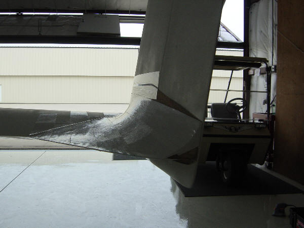
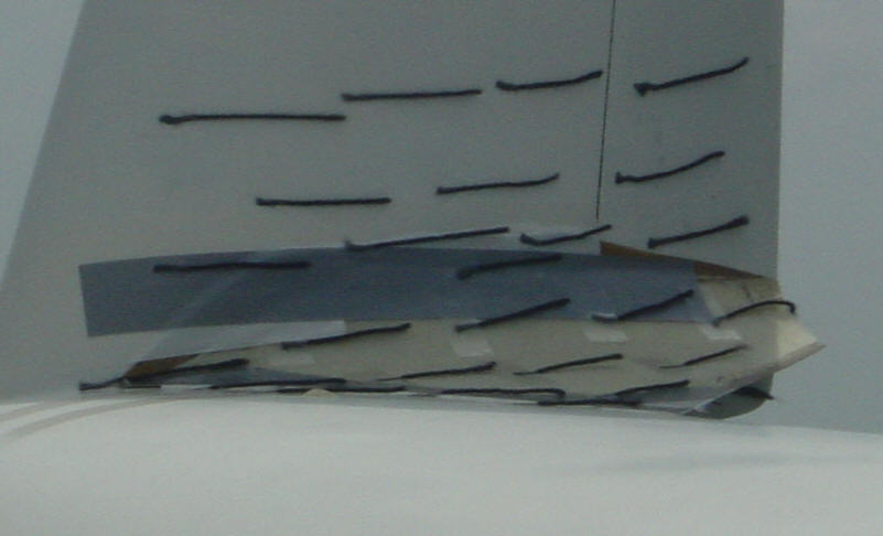
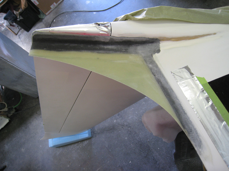
I took both of the Version 1.0 fairings off and re-masked and taped the areas for some additional testing. Instead of cardboard, I made same aluminum templates for the TE fence support. This time, I'm going to place the fence at the lowest position - level with the main wing TE. This position makes the TE up-tick much less acute and lowers the upper profile and resulting fillet. Once the position was established, I placed a 2-ply BID glass base over the area. The next day I added the lower 2-plys. You can see, this fairing is different that the first one. The profile is similar, but the angle is much less acute. After a quick trim job, I used some white duct tape to hold the splash on the wing, added the tufts and took it flying. The tufts indicated that the air was still separating at the wing max camber (as expected) but the fence seemed to help control the overall turbulence and lower side vortex. Not bad for just a TE fence. On to the next filet.
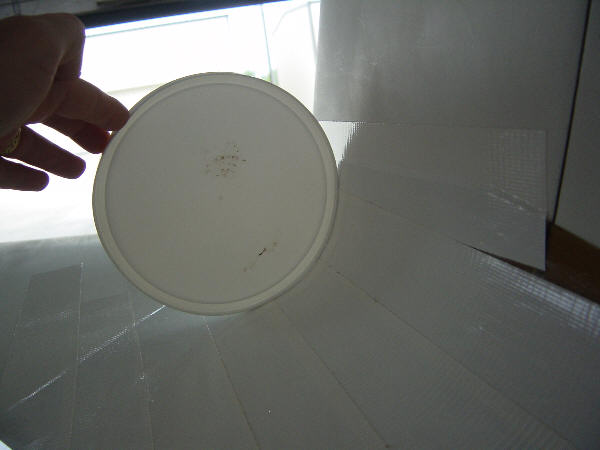
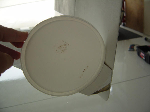
The building of the fillet was done the same way as before so I will not cover that here. Since I already had a data point on the Version 1.0 fillet, I wanted to see what a larger radius would do. So, this time I built a fillet with an extreme radius of 4". This is way bigger than would ever be used, but I wanted the data point at the end of the scale. I used a container lid for a guide for the radius and continued it all the way back to the TE. The whole thing was covered with white duct tape...and I went flying. Another mistake - the duct tape separated at about 140kts and created an interesting looking bubble. Holy blowfish, Batman! The testing was immediately aborted but you can note that the air flow was actually pretty good until the tear in the tape. I put a single ply of BID over the top surface, and did the testing again. The airflow was amazingly good. I was shocked! Well...until I did the performance tests. Due to the tape attachment I could not attempt the max cruise speed tests, but it didn't matter. I used the asymmetrical drag test to determine that the large fillet was producing MORE drag than the un-faired winglet. It was simply too big...as I expected...but now I know for sure. I ran out of time and have not done any other experiments to date - I would like to use this fairing again, but with a smaller radius and test again. As soon as I get a week or two (three years later) of time freed up, I'll build the Version 3.0 fairing. It will likely be the same fillet size, but with a TE point much lower than the original and a slightly smaller radius.
Status: Version 2.0 Tested - temporary tests only, incomplete, additional radius tests needed
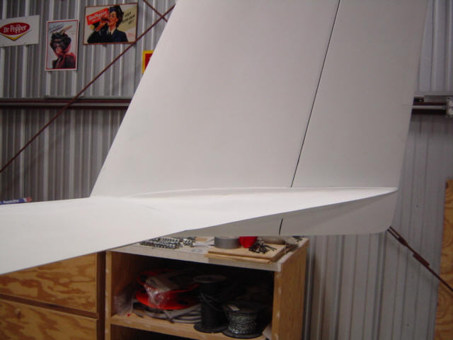
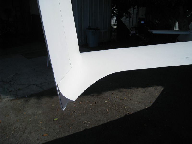
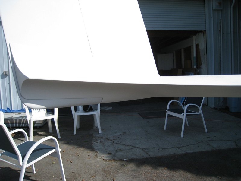
Final Version: (11-08-11) It's been a few years, but I am finally getting around to finishing all the external modifications to the airplane as prep for painting. So, that means that the intersection fairings will finally get some attention. I had brought the original version 2 test fillets with me to CA that already had the trailing edge at the correct position but had the larger higher drag radius. So I just peeled off the 1-ply of glass on the tops, re-contoured the foam and re-covered them. The flight test went great with the tufts nice and flat indicating good flow and lower drag. Again, this configuration proved to be less drag than the opposite un-faired winglet. I took the wings off and brought them inside the EAA room to work on because this process was going to be a little more involved than the temporary models.
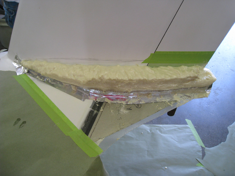
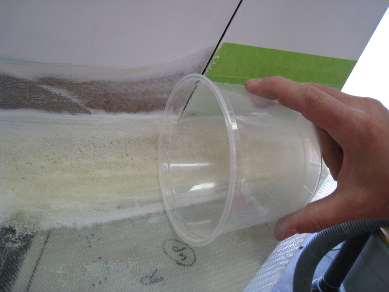
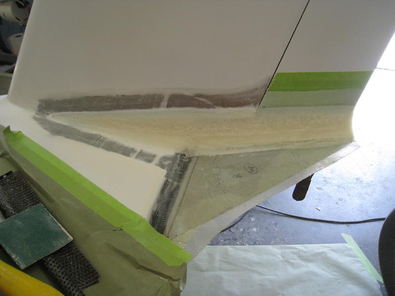
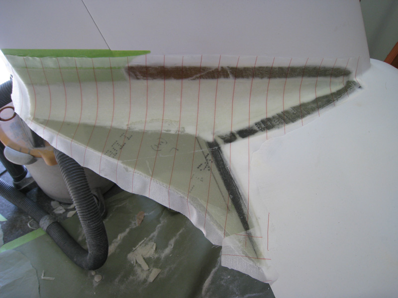
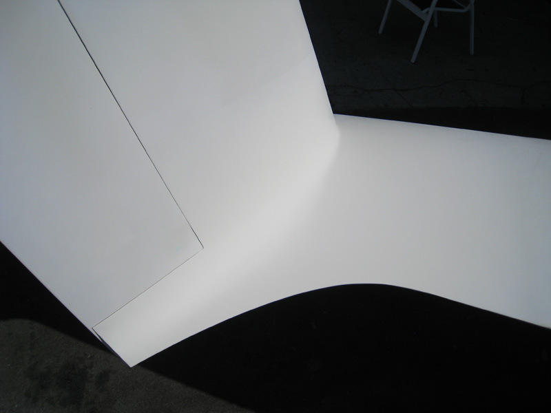
I started out by sanding out the micro on the wing's trailing edge and mark off the perimeter of the bonding area. I also put down some packing tape on the rudder as release material for the closeout plies. Then, proceeded to put down a 2-ply glass layer on the rudders - this becomes the closeout for the fairing. Once that cured, I used a metal forms to support a 2-ply base layer that bonds to both the wing and winglet and becomes the common surface for the fillets. To form the radius, I used some aluminum tape to form a dam and two part pour foam in the corner. I used a plastic mixing cup to check the 2.5-inch radius of the main part of the fairing. The radius starts very small at the front and expands as it tails aft to the wing's trailing edge, then remains constant all the way aft. This configuration seemed to yield the best flow results. Once I was happy with the radius, I put the final 2-ply top laminate over it all, also bonding to the winglet and wing and covered with peel-ply. I removed the peel-ply when it was still green and added West micro filler to get a chemical bond. Sanding, sanding, sanding...then the tops were complete. They really started to look good once I shot the primer on them.
The bottom side was easier. I added a 2-ply carbon L-tape to the lower fence to improve it's rigidity in conjunction with a 2-ply glass layer. I had a brainstorm idea (more on that later) during this process and added a phenolic hardpoint in the fairing's TE section and closed it out with flox/micro mix and a ply of glass. I wanted to make the lower section a little more faired, so I chose a section of 2 3/8-inch diameter tubing to create a pleasing mini-radius on the bottom. Micro..sanding..sanding..and the bottoms were done. Shot some more primer..and the results were better than I expected!! aft view, side view, top view.
Oh...the brainstorm...yeah, I got a two-fer on this mod!! Since the winglet fairings and the rudder both end at the same location, I came up with a rudder lock that takes advantage of that. Whoo-hoo!
Status: Version 3.0+ Complete - Measured similar speed gains of 3-5mph but with better flow indications, speed tests skewed to higher end of range, permanent
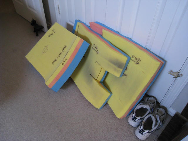
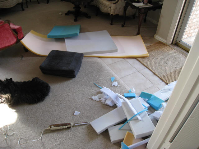
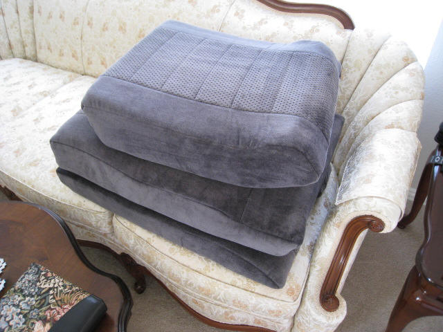
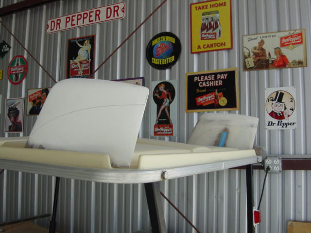
Seat Foam Replacement = 13lb. Weight Reduction: (4-8-08) For the last few months, I have really been working to find things (or ways) to reduce the weight of the aircraft and more importantly shift the CG aft. So, I got the digital scale out and started weighing things. I was AGAST to learn that my current seat cushions weigh a total of 26 POUNDS!!! Man, that Confor foam is heavy stuff! Too heavy, in my opinion, and it's all forward weight. Time to do something about that! So, I brought them home and pulled all the old Confor foam out. Since the seat covers were already there, all I needed to do was to use the originals as templates and cut up some automotive foam. A few hours later, I had the seats completed and put them on the scales. I was shooting for a 50% reduction in weight, and I got it and then some. The total seat weight went from 25lbs, 13oz to a more realistic 12lbs, 13oz. That's a weight savings of exactly 13lbs. (shocking number, huh) and that's significant enough to notice on the CG. Here's the spreadsheet with all the details. Of course, when racing the short sprint races, I'll remove the rear seat completely and save even more weight. Every little bit adds up with this stuff, and this was a simple mod that makes a noticable improvement. I don't expect the new foam to be quite as comfortable as the Confor foam, but the Confor foam has it's own problems and was not perfect. I've flown the new seats for over an hour at a time with no discomfort at all...in fact, the new seats are more comfortable in some regards - now with side bolsters, lumbar support, and Velcro attachement to the fuselage. They are definately keepers!
Status: Complete.
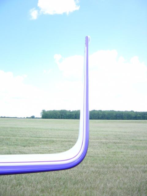
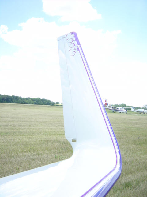
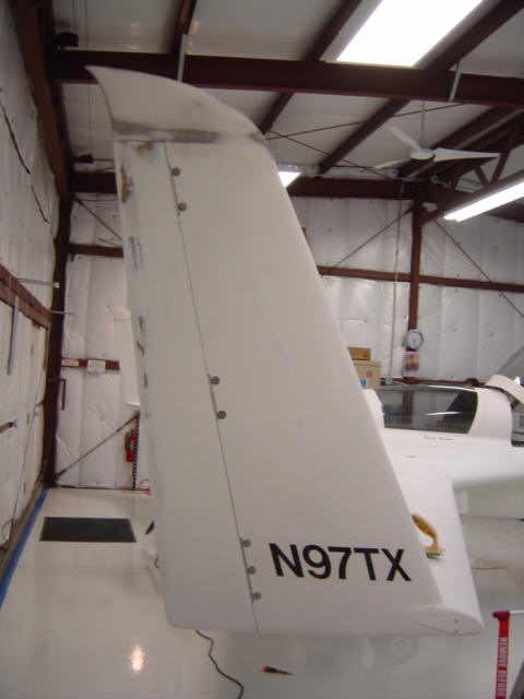
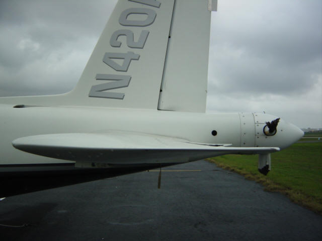
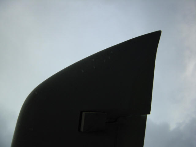
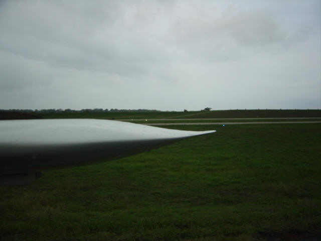
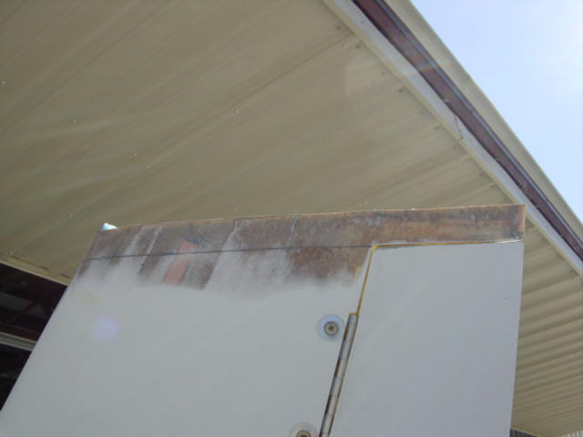
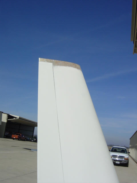
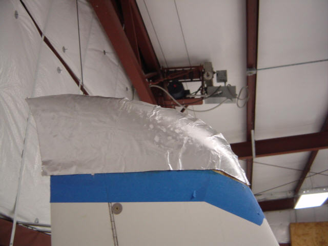
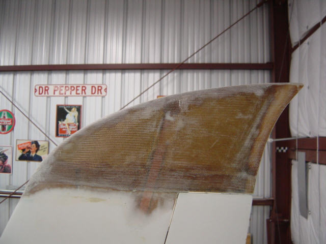
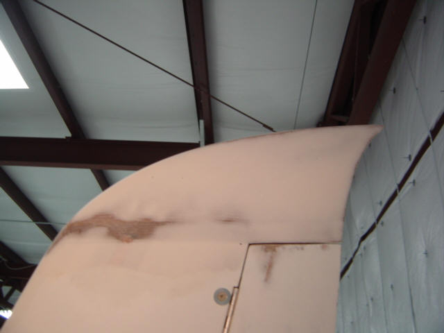
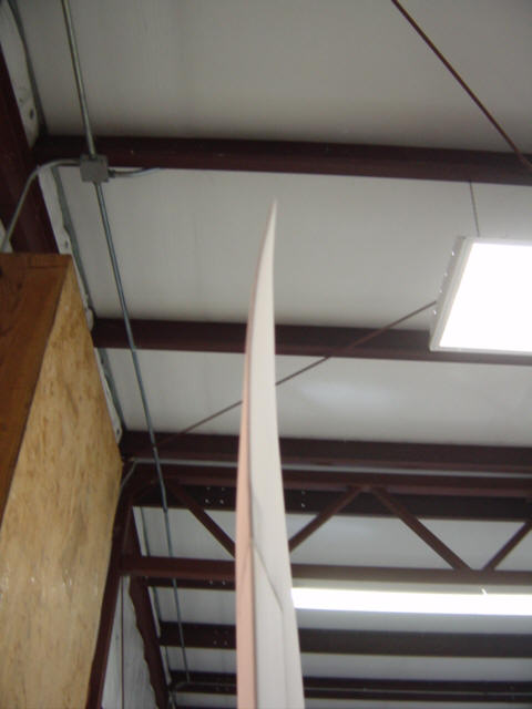
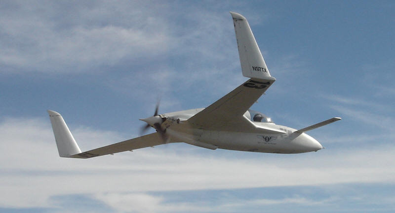
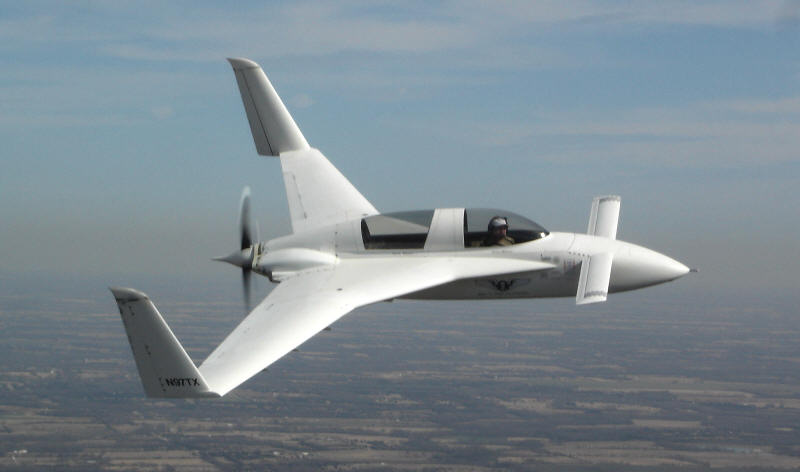
Low Drag "Snarky" Winglet Tips: (4-6-08) What's different about this picture? Less drag, that's what. I had been lamenting one of my second place "victories" and was wondering what I would do to the Berkut to make it faster but that would not take months to complete. I looked up and suddenly realized that the original winglet tips were just simple rounded shapes and had been the standard for more than 30 years. When I looked into where the shape came from, I found that the tips were just simply made to builder taste and really have no science behind them. I targeted them as easy pickings, and started gathering research. Hoerner has a whole chapter on wing tips and vortex drag. I read it, re-read it and kept looking. I noted the wing tips on a Cirrus VK while at the Memphis race. It had a very sheared and tapered design that I liked. The sheared tip was well discussed in Hoerner's book. The Rutan designed Aries and even WhiteKnight also had sheared tips...there must be something to this. A little more history - the original Berkut winglet was made little taller than the EZ to help keep the longer fuselage stable in yaw. As it turns out, it wasn't necessary...but the plans were never changed to trim them down. So, my winglets were about 3 inches too long in span...something else I would be taking care of. I consulted with a few other canard gurus and my mentor Scott Carter and after all the data gathering was done, I had decided to create a span reduced, sheared, tapered, washed out and cusped wing tip. Hey, it's got ALL the good stuff, so it has to be good....right? RIGHT! Time to get to work.
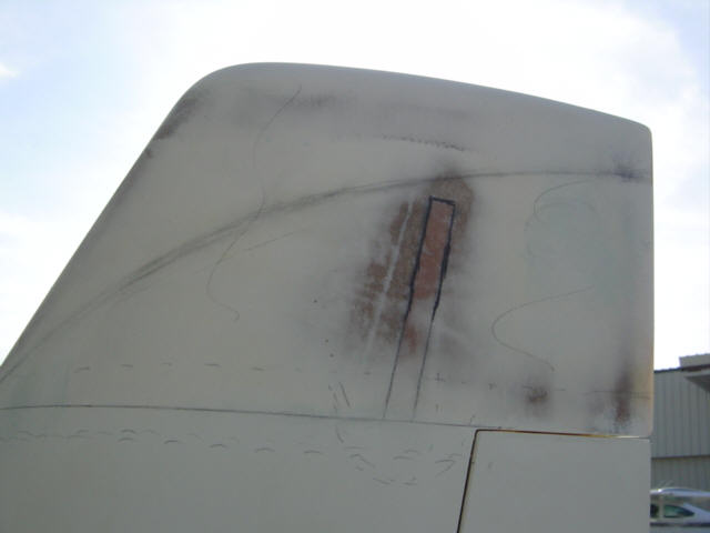
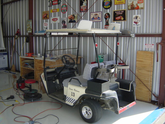
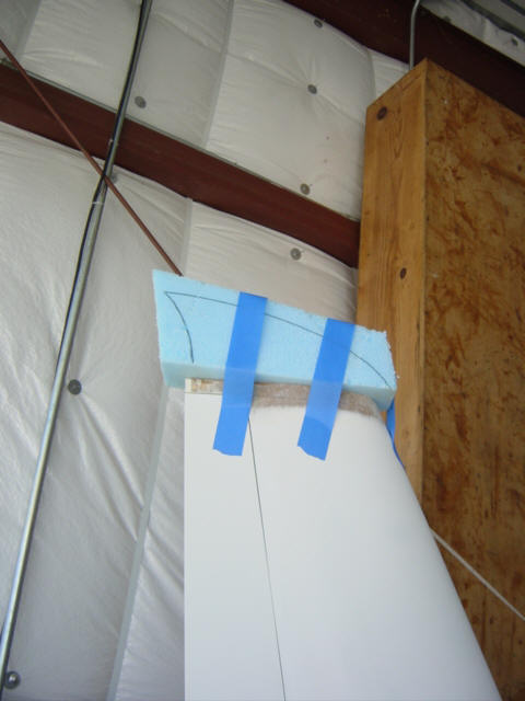
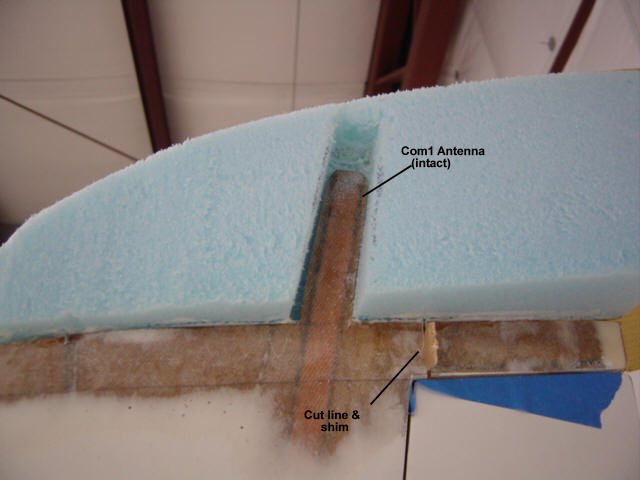
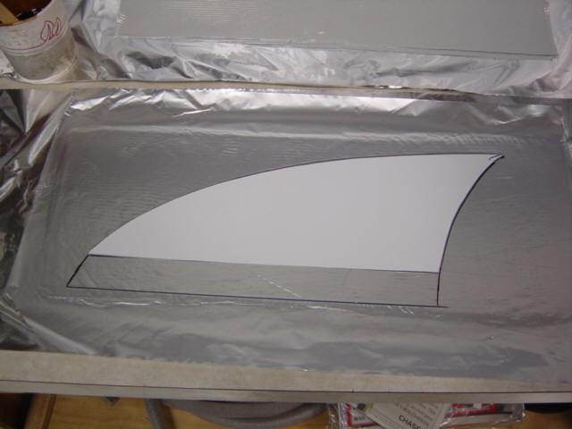
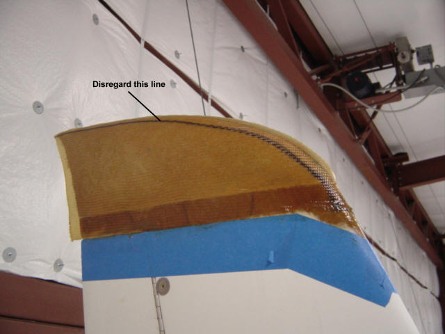
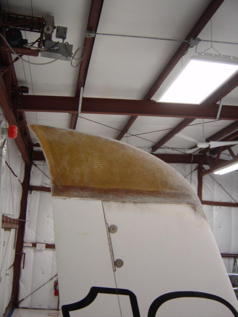
I made 3-4 templates out of poster paper and kept tweaking the shape I liked. I knew I had some issues to deal with too - like the location of the com radio antennas buried inside the winglets. I sanded through the primer and micro and exposed the antennas so I knew where I could position the template, drew the contour lines and came up with something like this plan. (that second antenna is going to be a problem) Now, all this data gathering and planning took about a month and the locals were included in it. So, I had a small crowd gathering around the Berkut as I sanded. They couldn't believe I was just going to cut off a chunk of flying structure...but, I did. ;-) The winglet looked a little strange...and short...with the tip removed. Scott Carter stopped by and encouraged me to cut more off...but I was satisfied with the cut line being 1" above the rudder. Some may ask what I did the with tips I cut off...well, here's the answer. HeHe...Scott's comment was "There he goes, cutting parts off a perfectly good airplane just to make his golf cart look good." Yeah...that's me.
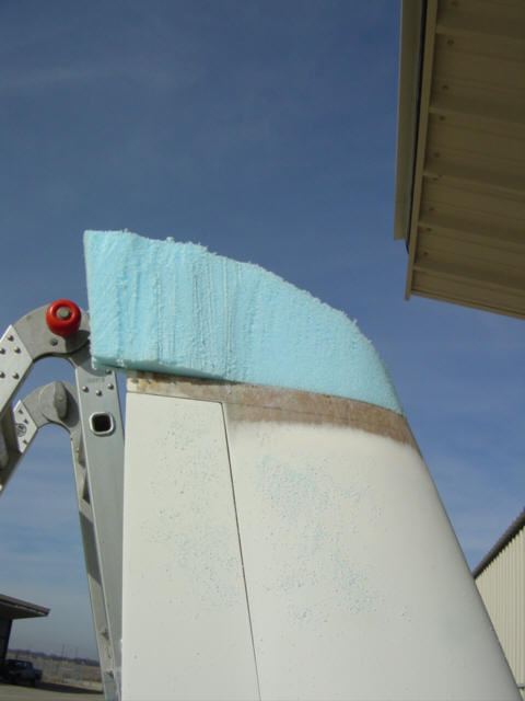
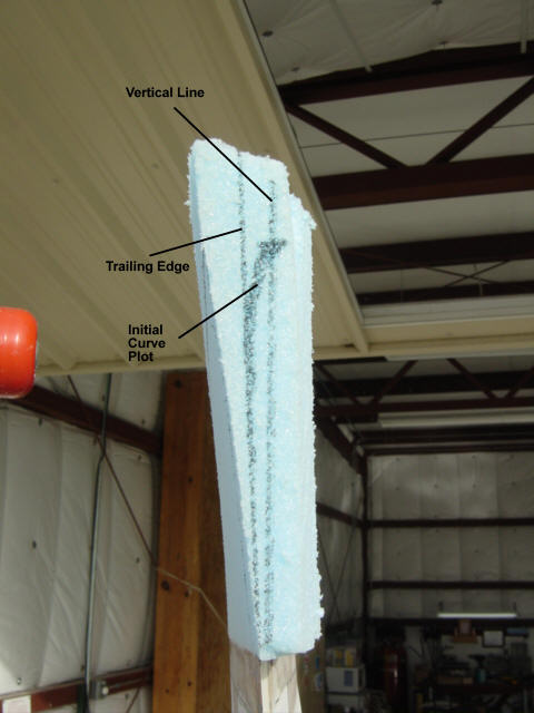
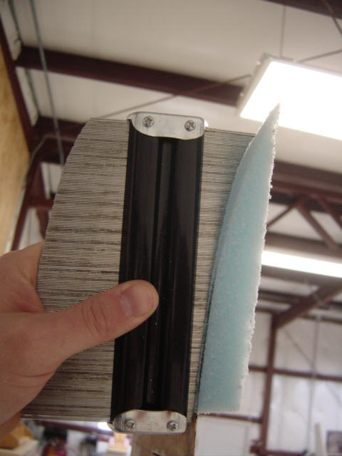
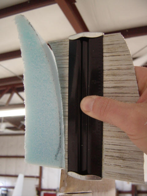
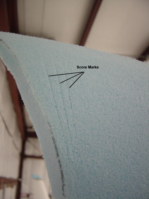
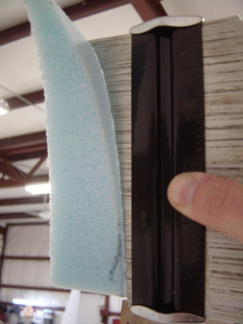
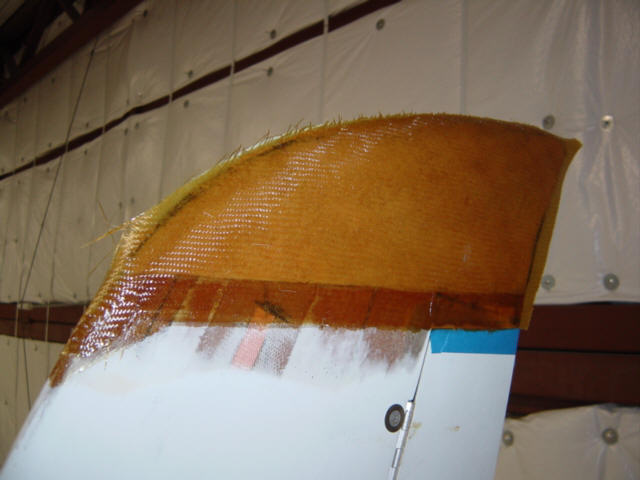
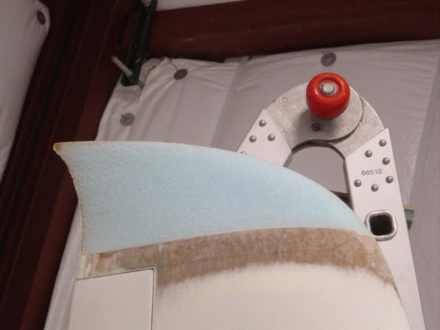
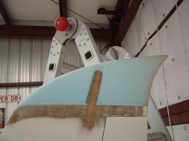
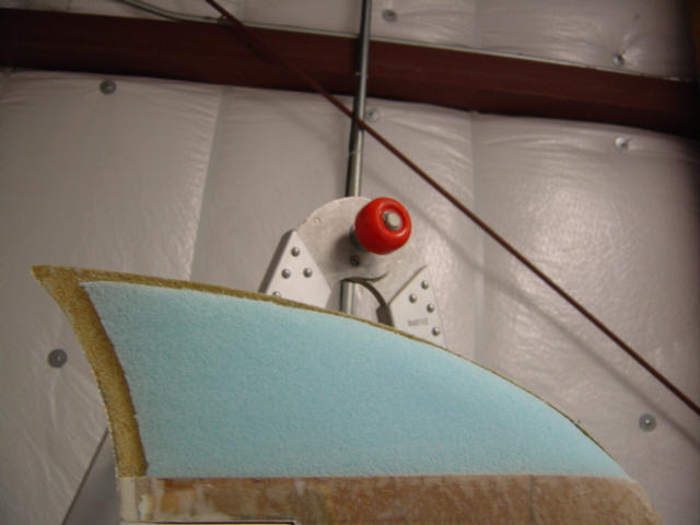
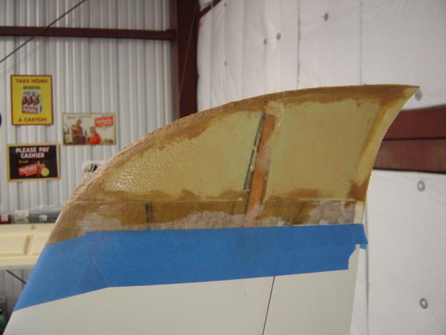
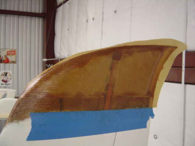
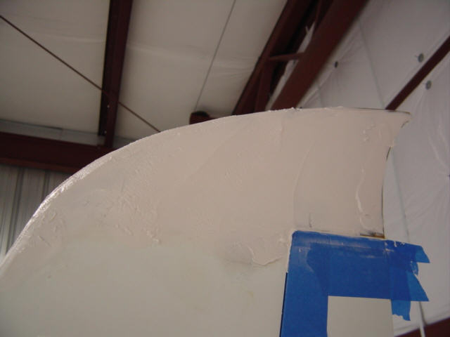
Rebuilding the tips was an exercise in sculpture. I first took some blue foam blocks and microed them to the top of the winglet. The right winglet's comm antenna required a cut out for it to fit. Then, I started removing material and re-drawing the template design over and over again until the final shape started to appear. The outside surface was the easiest so I did it first. Remember, the inner side is the one that gets cusped, tapered and sheared aft...yikes! So, I marked the top and sides of the template on the foam, then noted that the Berkut winglet is canted 4" outboard from vertical at the trailing edge. This ended up helping me - I just made a vertical line on the aft side of the foam, along with a line showing the T.E. of the winglet...then drew a pleasing curved line. This would become my cusp shape. The rest of the outboard foam was sanded away until the basic tip shape. Speaking of shape...now I have to do it all again on the other side...and do it the SAME. I got out the handy contour tool and made a measure on the left. When I tried it on the right, it showed exactly where I need to re-shape. All I had to do is press the needles into the foam to make a mark, then sand until they were gone. I repeated this process until the curves were the same. The foam itself was getting a little thin and was starting to bend as I sanded it - time for some structure. I wet out 2-plys of glass BID on some aluminum foil and covered it with another layer of foil so I could trace out the template shape on it. Then, after putting some slurry on the foam, I applied the BID onto the foam. There was a full inch of structural bond line and I left the excess material alone - to be cut off after cure. And the other side was dome the same way.
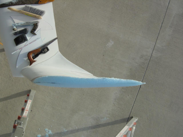
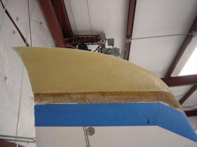
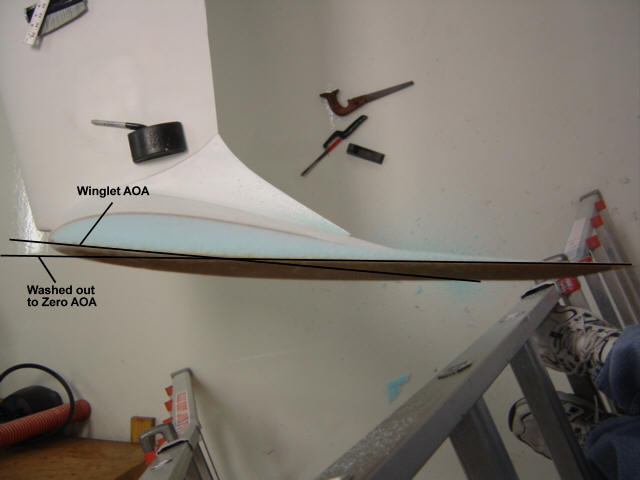
After an overnight cure, I started sanding the other side. There is no way to describe this in a linear fashion because of the multiple curves and shape fairing. Basically, I started with a basic taper to the top, then faired in the foam to meet the aft end of the cusp. Kewl, huh. Now, I also had to factor in the angle of attack wash out (seen from above) - which is basically means the whole tip is twisted so that the upper edge is at zero-AOA to relative wind. So, you can imagine there is alot going on here. The com antenna on the other side made it more difficult to carve, but I managed to get it right.
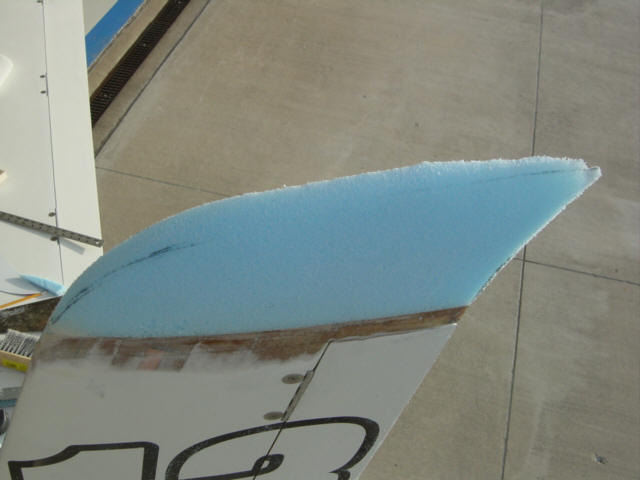
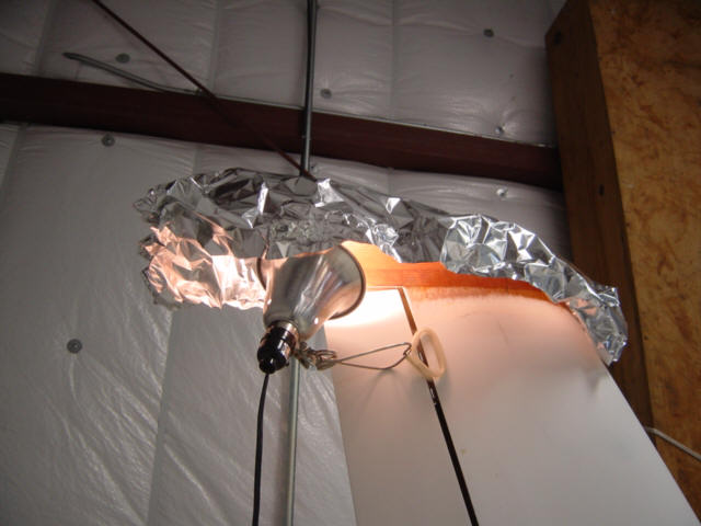
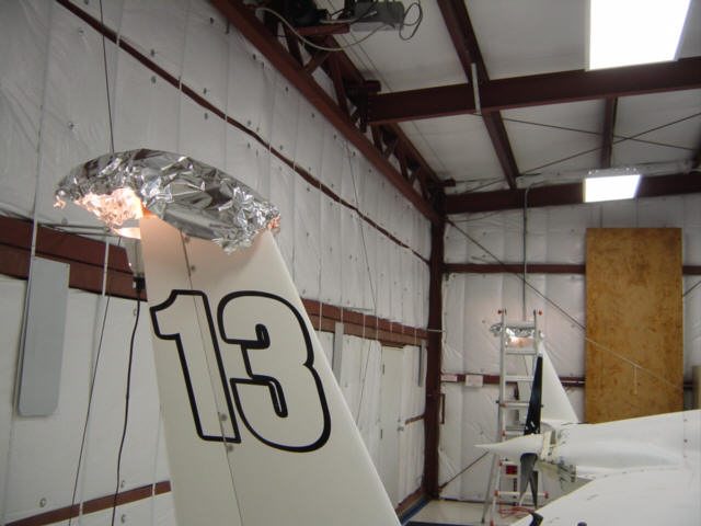
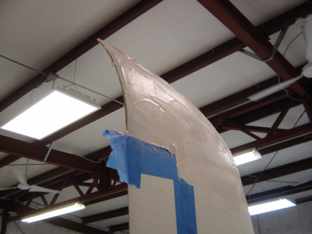
I didn't want to over lap the BID plies, so I cut out some of the foam around the edges of the tip and filled them with flox. Some slurry and two more plies of BID and it was looking good. It was pretty cold at the time, so I devised some EZ-bake ovens and cooked the tips overnight. The next day, I trimmed off the excess and sanded away the snags and suddenly I had some winglet tips again! Well, they still needed filler...so I covered them with West micro and wondered what they would look like finished. Well, that would have to wait - back in the EZ-bake ovens again.
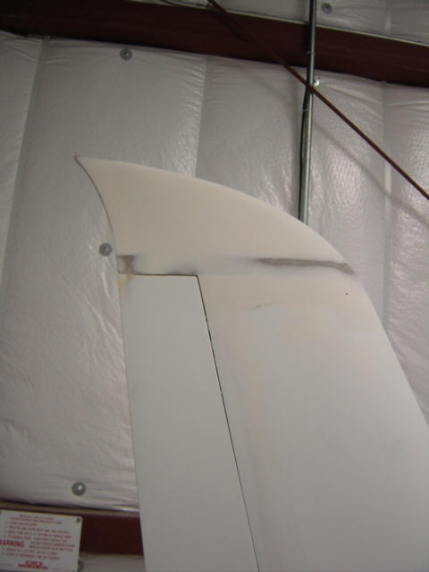
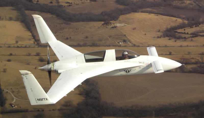
A few hours later, I started sanding and re-sculpting the tip and...oh, boy...these things were looking GREAT! Check out the trailing edge. The sides look rather good too - right, left. OK...OK, I have to admit, I really didn't think these were going to turnout as well as they did. Man, they change the look of the whole plane - very Snarky! Definitely a Ramp Speed Factor of 10!!!
Before putting primer on them, I just HAD to take them for a spin. Here are some in-flight pics - aft view, side view and at cruise.
Status: Complete.
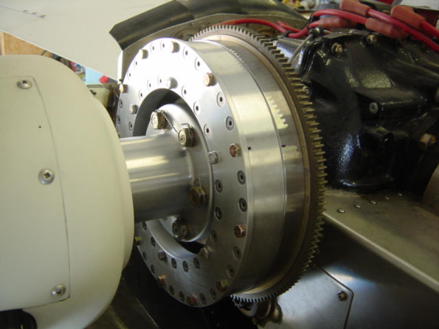
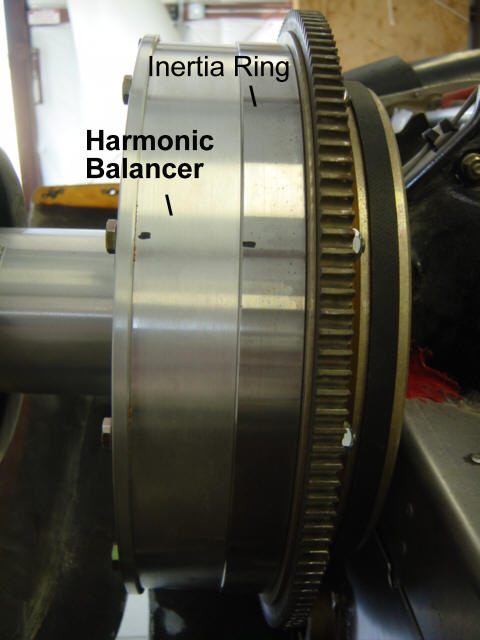
Harmonic Balancer & Inertia Ring: (4-20-08) As with the seat foam weight reduction, this modification's main objective was to add more weight (preferably useful) to the aft end of the airframe to move the CG rearward...any additional benefits were secondary. As it turned out, the "secondary benefit" was the best part! First, let me tell you that I too have heard all the stories about these devices not doing any good and are not worth the money and I was VERY skeptical going in. To all those nay-sayers...I say, Horse Hooey!!! It performs perfectly for me! The difference is black and white in my book and will sure not be taking this "weight" off my plane.
These units are made by Mark Landoll of Newcastle, OK. Since additional weight was the goal, I ordered both the harmonic balancer (12lbs) and an inertia ring (10lbs). The harmonic balancer consists of a steel ring suspended in a silicone fluid encased in an aluminum housing. The inertia ring is just a large steel ring about an inch thick that bolts onto the harmonic balancer to increase rotational mass. Both of these devices are stacked up and bolted onto the engine's flywheel with several Grade-8 bolts. Here is a detailed picture of the assembly. They both work together to smooth out the power pulses (inertia ring/mass) of the large bore engine with a low mass prop, and dampen the harmonics (balancer) generated by the engine/propeller pulse coupling. So, it's not quite the same as a dynamic prop balance, but it does help to dampen the hiher order harmonics through-out the full RPM range.
I have tested and flown extensively with a raw propeller, propeller dynamically balanced, and now with this combo - the new combo wins, hands-down! It took a couple of hours for the balancer to break-in (as explained in the instructions) but the differences were felt from the first start. The engine will idle smoothly at a much lower RPM (650) and the additional rotating mass helps with starting. But the best part is that the faster I spin the prop...the smoother it gets! ;-)
UPDATE: I have since removed the inertia ring to...yeah, you guessed it...to remove some weight, but mainly to better fit the NTX Spinner. I will continue to use the dampener as the spinner was designed to fit it perfectly and the benefits are worth the weight.
Status: Complete.
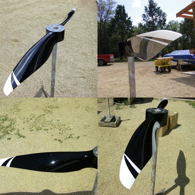
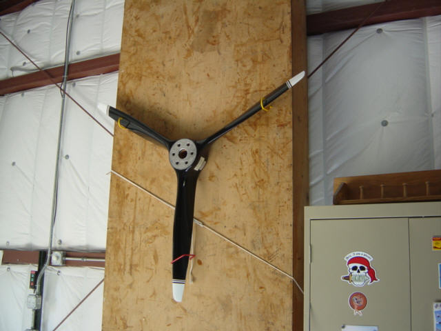
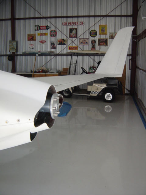
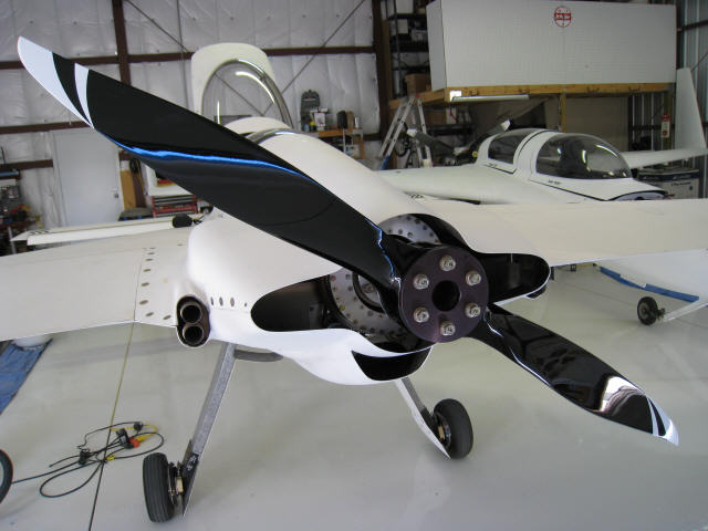
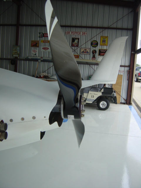
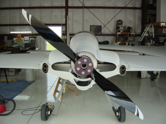
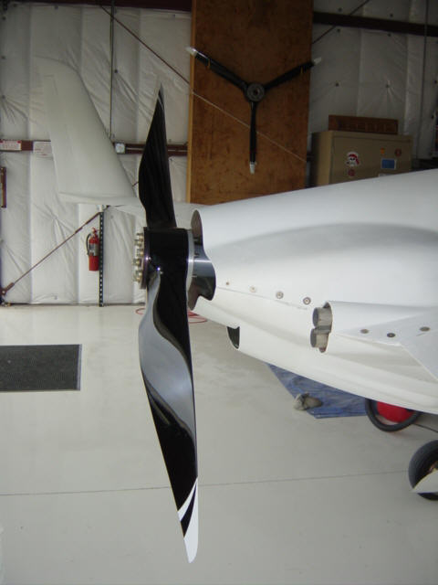
Custom 2-Blade Catto Race Prop: (4-23-08) Whoa, mom-ma!!!! I was FLOORED when Craig Catto sent me this collage of the custom race prop he was making for me. This thing is a wickedly twisted "speed stick"!!! So, even before it arrived, I took the venerable 3-blade and hung it up in it's place of glory. The Berkut was left wanting for the new arrival as well. The next day, I quickly un-boxed it, got the torque wrench out and a few minutes later - she was ready to do battle with the speed demons. Here are a few other views: Left, Center and Right. You can really see the curves in the reflections. The specs are, of course, classified. But, yes, this prop is FAST! The only down side is that I now have to build a new spinner for it.
Status: Complete. Race results pending.
NTX Pressure Recovery Spinner: (3-23-11) OK, this was such a big modification, I gave it a page of its own. Click HERE to go directly to it.
Status: Complete. Race results pending.
C.R.A.M. = Clean Ram Air Mod: (4-23-12) Of all the mods I have performed, this one has been the most successful in improving performance. I can measure a difference in all phases of flight, from take-off to high altitude cruise to LOP fuel burn. With the pressue recovery "CRAM" scoop, I get more boost WITH the filter installed than I did with the previous straight shot tube ram air system. The expansion of the air inside the scoop is the trick - exchanging the velocity for pressure before trying to do anything with it. Now, I get about 100RPM more on take off (by rotation), a < 1-inch MP boost at cruise, and BEST of all...I can now run 205KTAS @ 11,500ft @ 6.2gph!! That means I can make it from L.A. to DFW non-stop in 6.2hrs, without help from the wind, on ONE tank of fuel with VFR reserve. THAT right there paid for this mod in fuel savings alone!
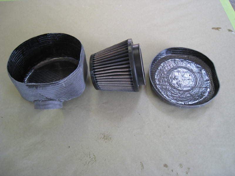
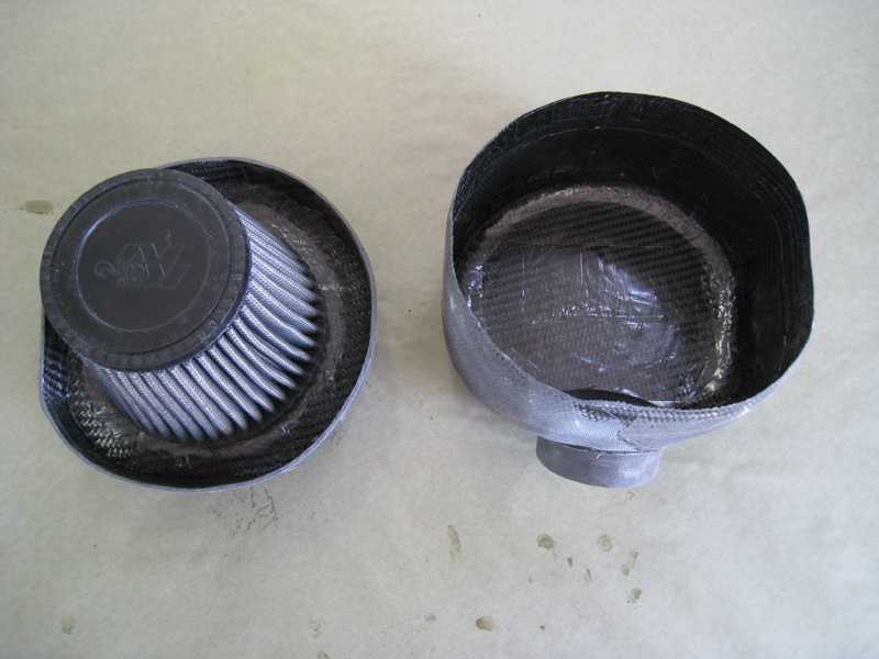
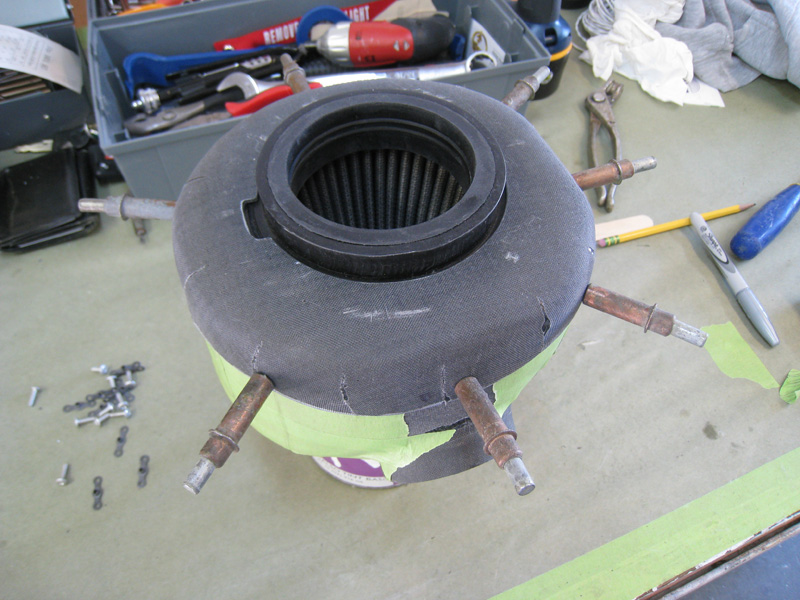
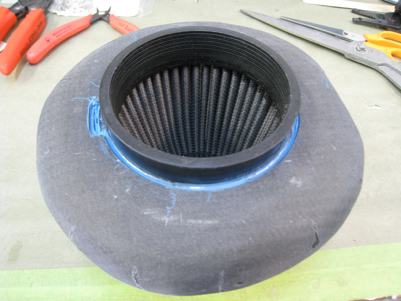
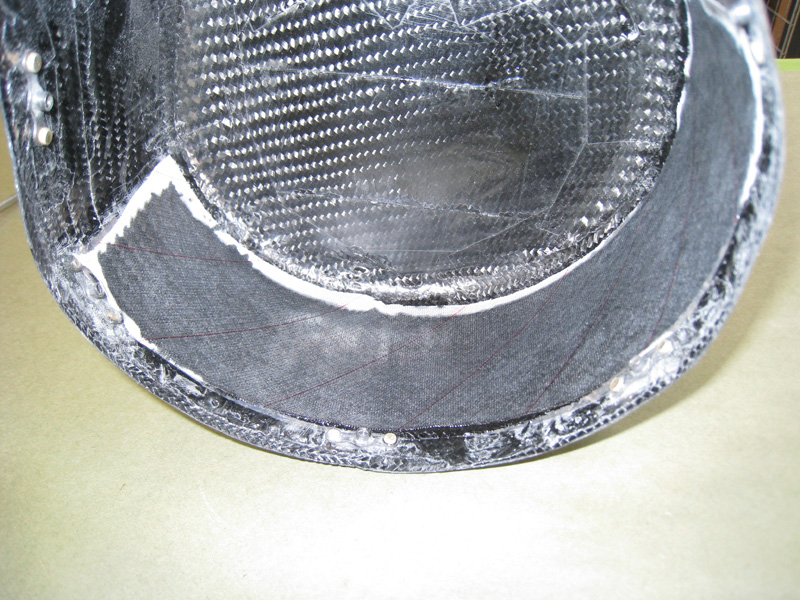
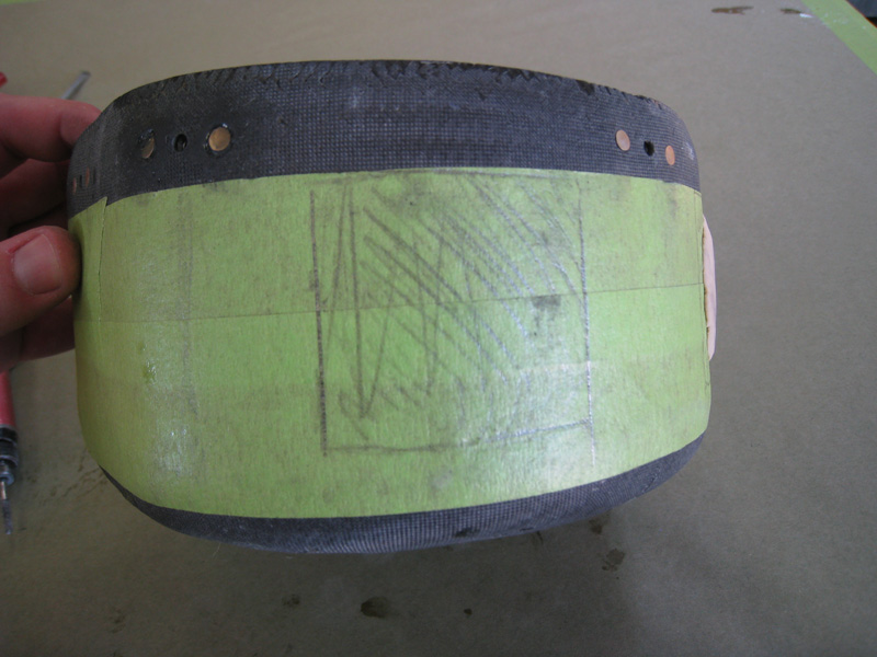
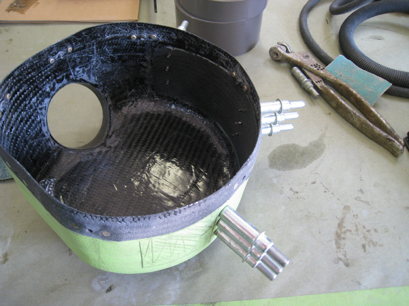
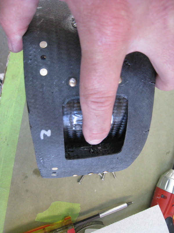
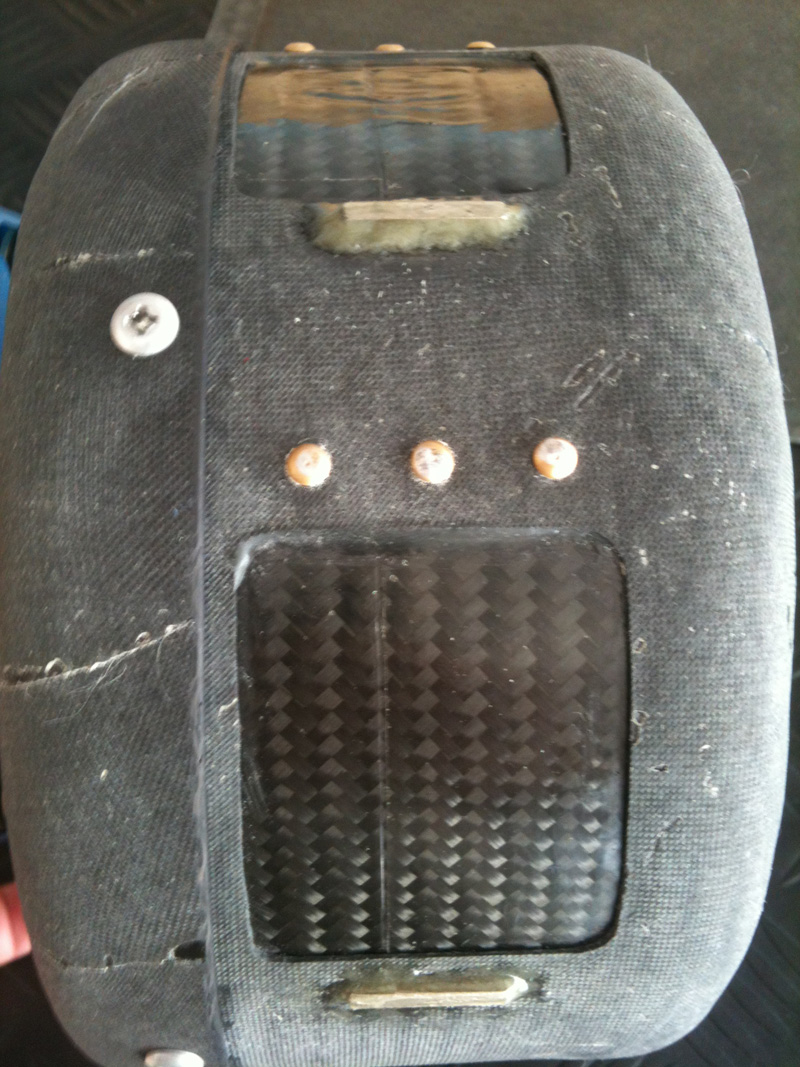
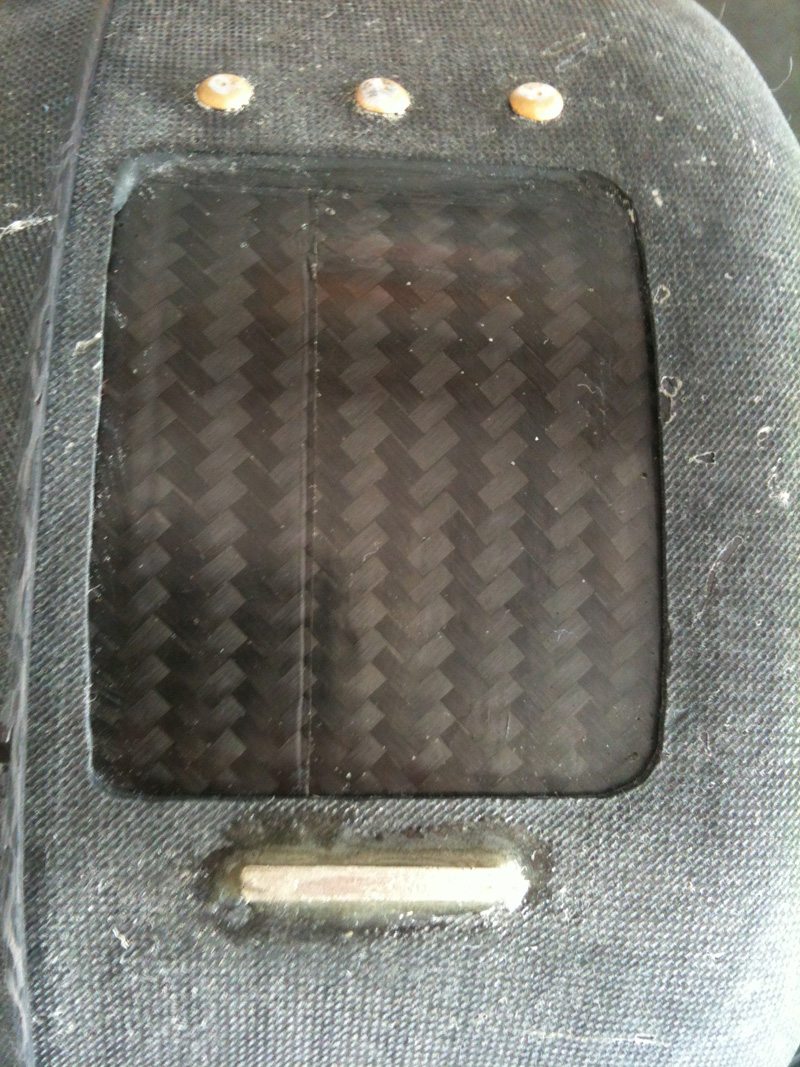
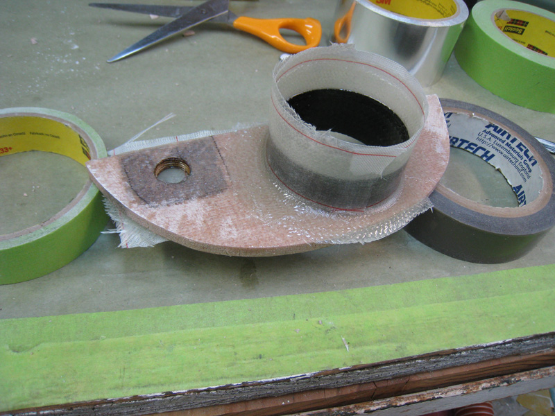
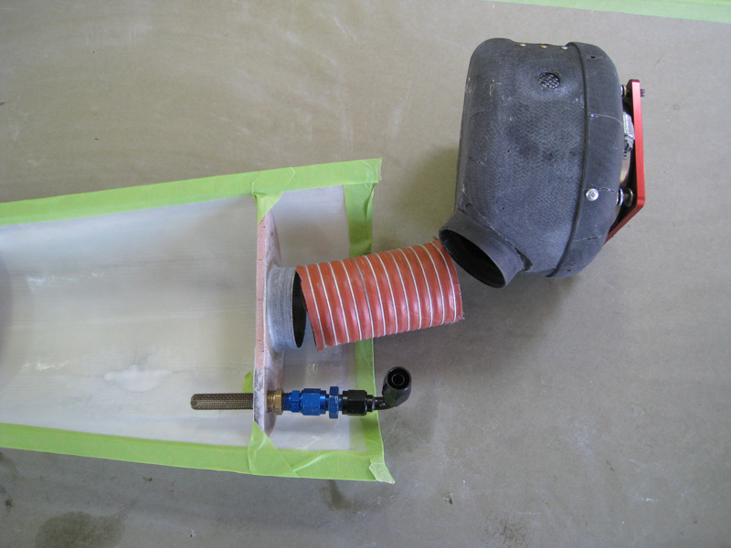
I started the system by building a pressure chamber for the K&N filter I already had. There was a little space around the filter area, so I carved a block of foam in a shape to use it all and determined where my inlet flange was going to go. I covered the foam plug with some release tape, layed up carbon BID over it and let it cure then made the base flange the same way but thicker. Once complete, I had two overlapping pieces that captured the filter. I cut a hole in the base plate and fitted the filter flange and performed a trial fit on the servo - IT FITS!. To finish up the chamber structure, I installed some nut plates around the perimeter and used oil resistant RTV to attach the base to the filter.
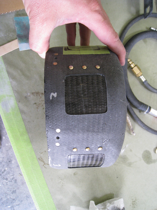
Now, because this was going to be a closed system, I felt it needed a alternate air source. Originally, I wanted to create a valved system where I could select filtered/non-filtered air...but there is just not enough room in this space to accomplish that. So, I settled for a simple, automatic, alternate air system using 'reed valves'. I layed up a strip of 3-ply carbon around the inside of the chamber and drew out the openings on the outside parimeter at the top. After cure, I installed some clecos to isolate the strap's location and fit. I had planned for 3 openings, but a quick area calculation determined that I could get away with only two - so, I cut the two openings and kept the 3rd in reserve (not needed). The carbon strap is only attached at one end, so if the main scoop opening is ever clogged, the engine's mechanical suction will draw the reeds open and allow air to flow freely. I tested this on the engine at max static RPM (2300) and pulled the reeds open about 3/4 inch with no change in engine performance - no need for the third opening. I also added helper magnets to the end of the reed and the outside opening. Now the valves snap open and closed, and stay closed during normal idle. A good, simple addition that makes them operate more positively.
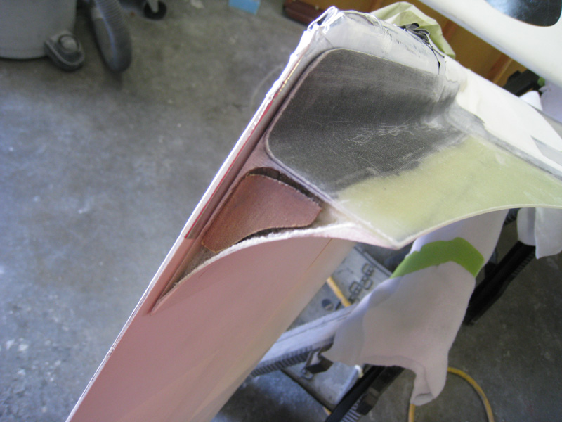
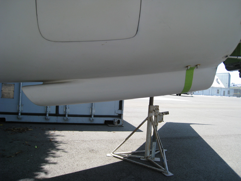
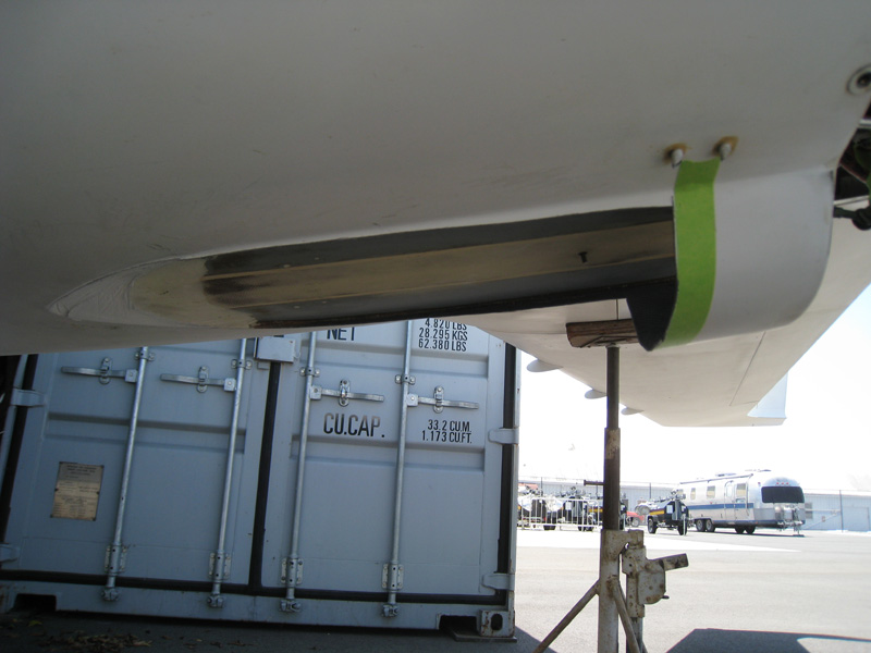
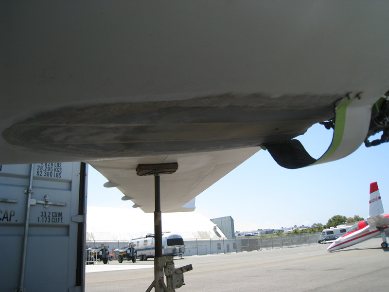
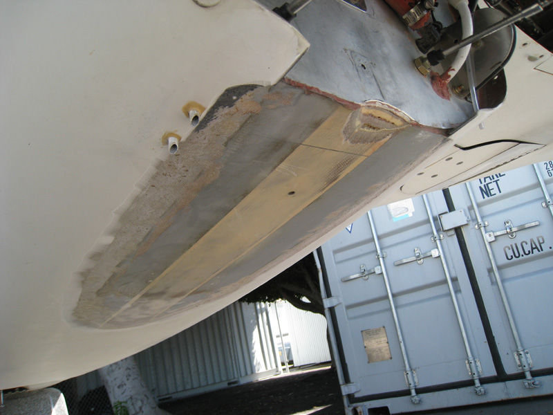
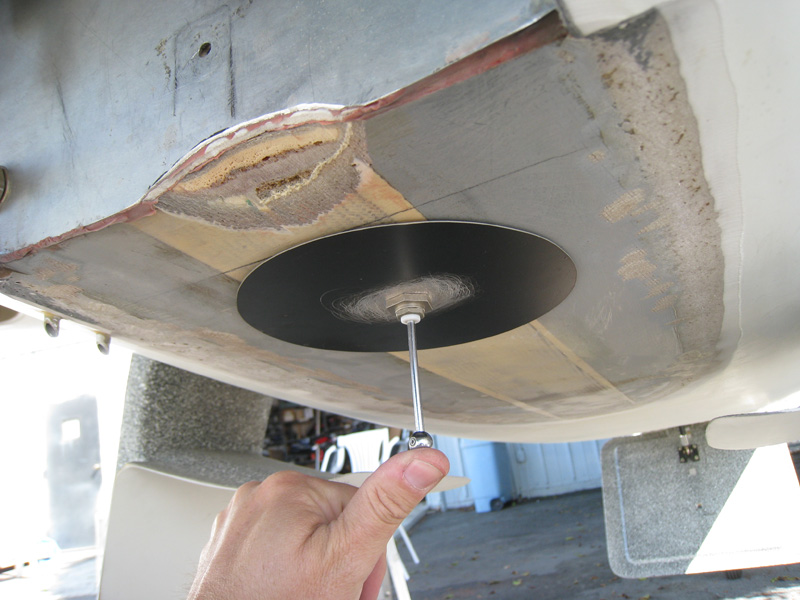
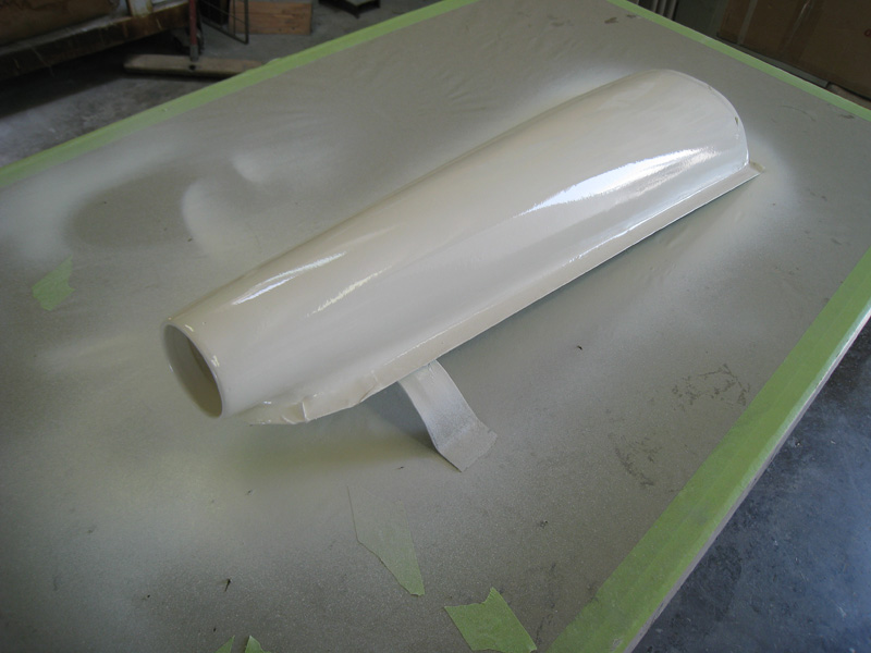
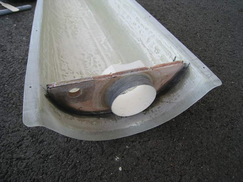
The important part of this mod is actually the pressure recovery scoop. The standard Berkut belly scoop typically just dumps into the lower cowl along with the arm-pit scoops. There are several issues using more than two balanced scoops in a plenum...but I won't get into that here - needless to say, it causes more problems than it solves. I had already tested the Berkut's performance with the belly scoop closed off and was happy with the results (cooling actually improved)...so deleting it was only a benefit. So, I grabbed a air-saw and cut the bloody thing off and sanded out the bond area. I wanted the new scoop to match the existing ridge in the lower cowl, so I left cowl mating flange so I could fabricate and mock-up the aft bulkhead, flanges and fittings. I even used a finger screen to keep debris/bugs out of the injector pressure reference hose (see turbo injector section for more info). After I was happy with the placement, I removed the remaining scoop flange. Since this scoop was going to be glass (not carbon like before), I took the opportunity to move my transponder antenna into the 'no-drag' area (a two-fer bonus) while the scoop bulkhead additions were curing.
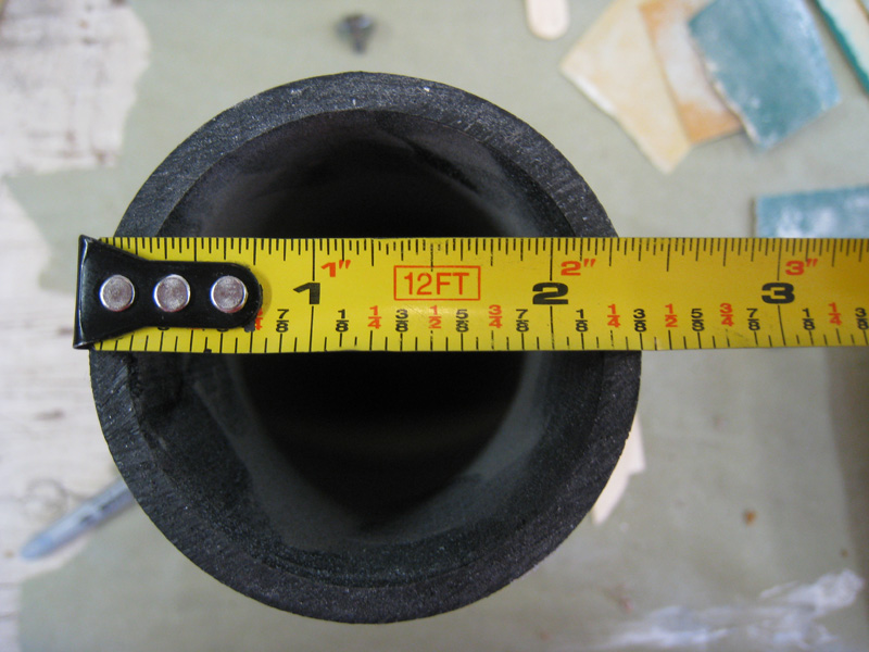
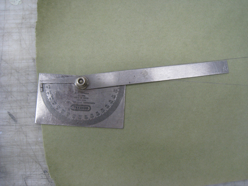
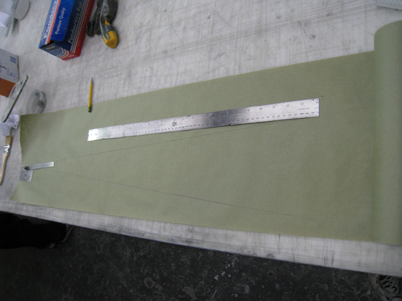
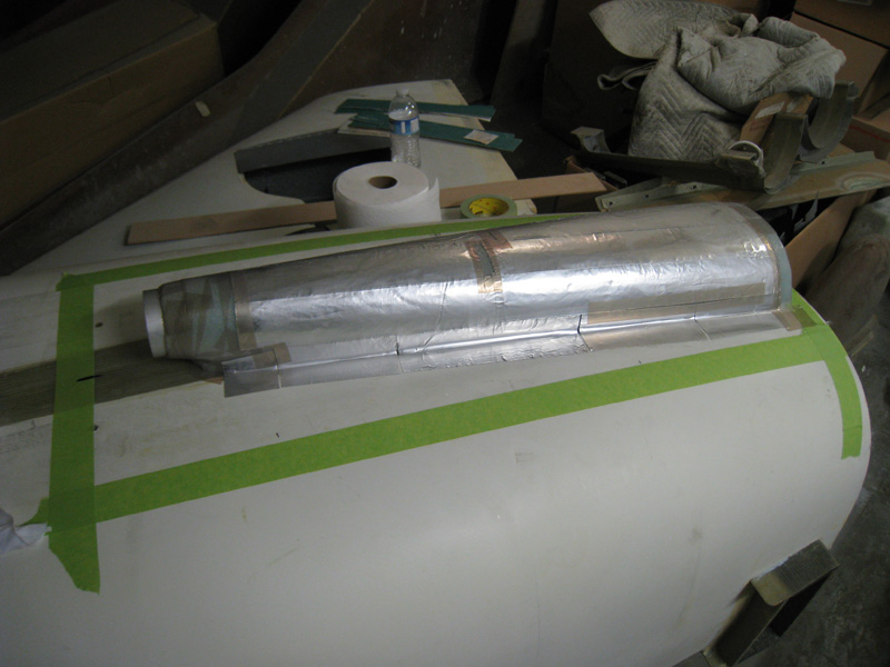
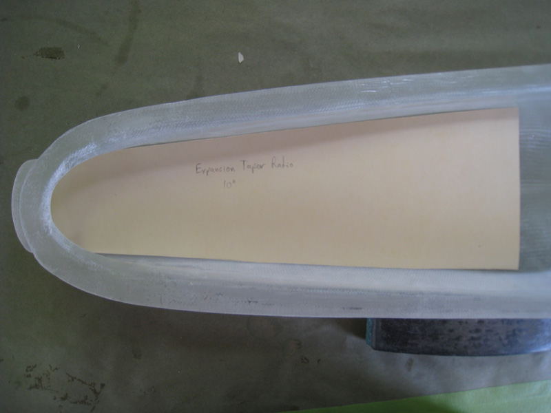
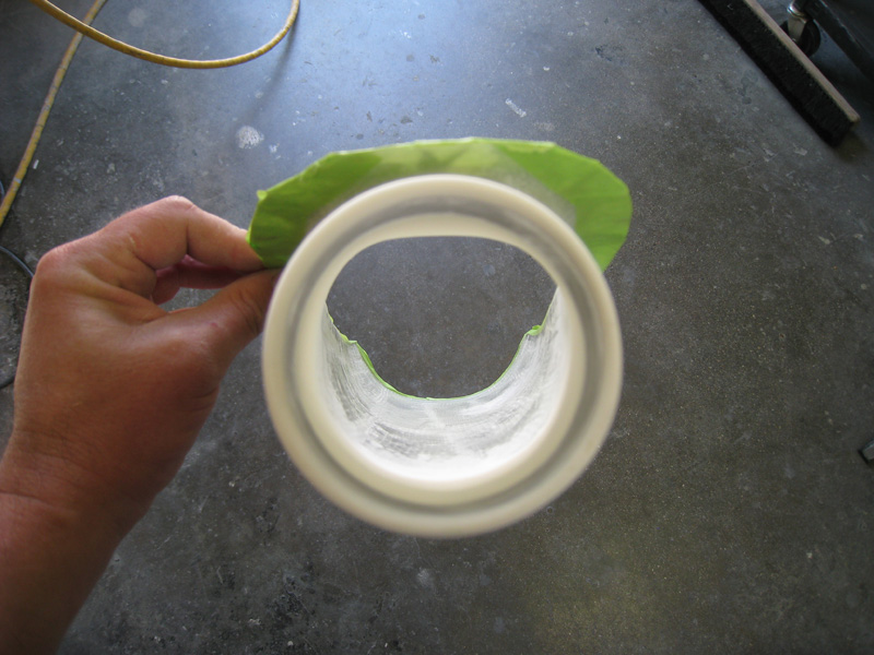
For the pressure recovery scoop to work, it is important that the angle of expansion remains below 11 degrees so that it doesn't become turbulent as it expands. So, I got the protractor out and created an angle template and worked backward from the lower cowl opening (maximum width) to determine just how long the scoop would have to be with an opening the same as the Bendix servo. The foam plug ended up only being a few inches longer than the original scoop and basically the same height - that's good because I didn't want to change the Berkut's signature profile lines.
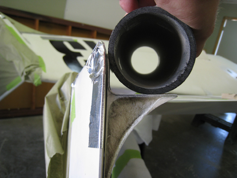
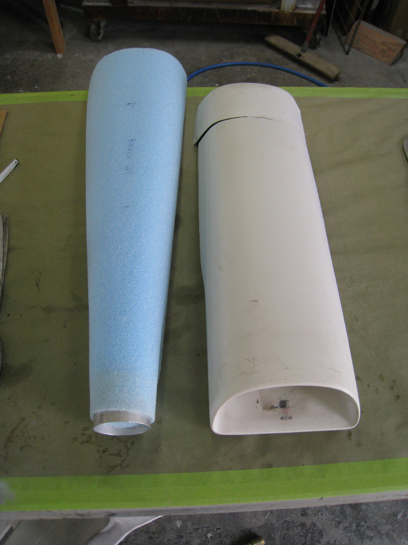
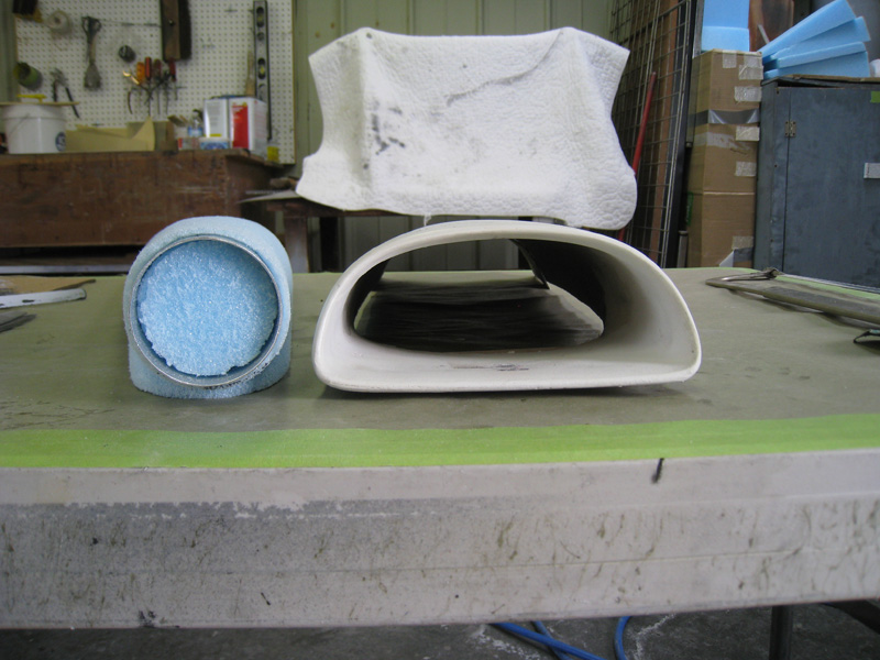
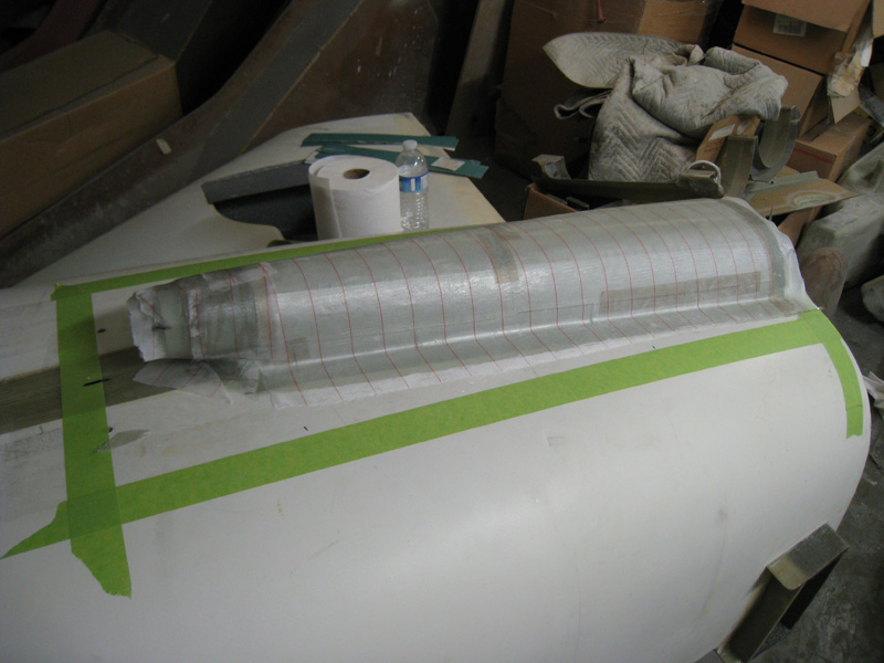
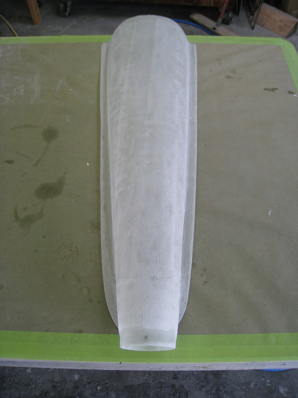
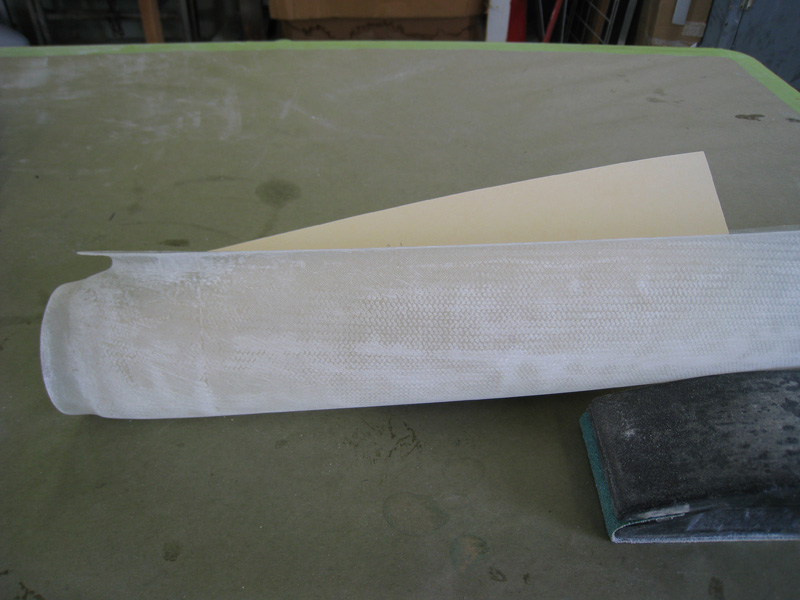
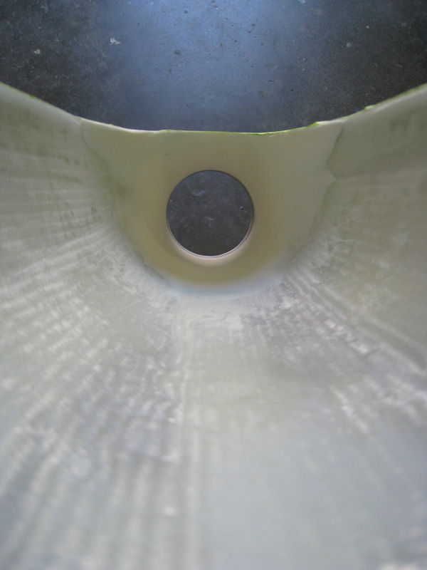
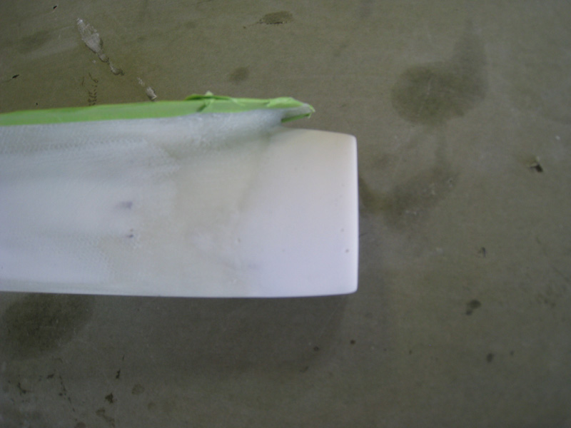
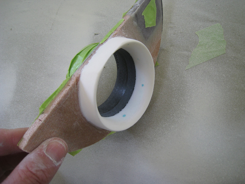
I was working at the Berkut Engineering & Design at the time, so I was able to take advantage of an old mock-up fuselage up in the loft - beats doing this upside-down! I put the foam plug on the fuselage, covered it in aluminum tape, created a edge radius and a flange, and layed up 3-ply BID glass and peel-ply. After sure, I removed the foam and had a raw scoop to work with. I double checked the horizontal expansion ratio as well as vertical - both 10 degrees or less. I left a small portion of the aluminum tube in the intake end to give it some strength and used micro to shape a smooth fillet inside the opening and on the exterior. A little primer later and the parts were ready to install. However, a quick consult with Gary Hertzler and Terry Schubert indicated that I really needed to smooth the inlet opening at the scoop bulkhead - this would keep the air from tripping over the sharp edge. So I piled up some micro and shaped fluted inlet flange (bell mouth) and rounded all the edges.
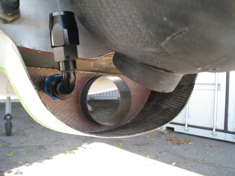
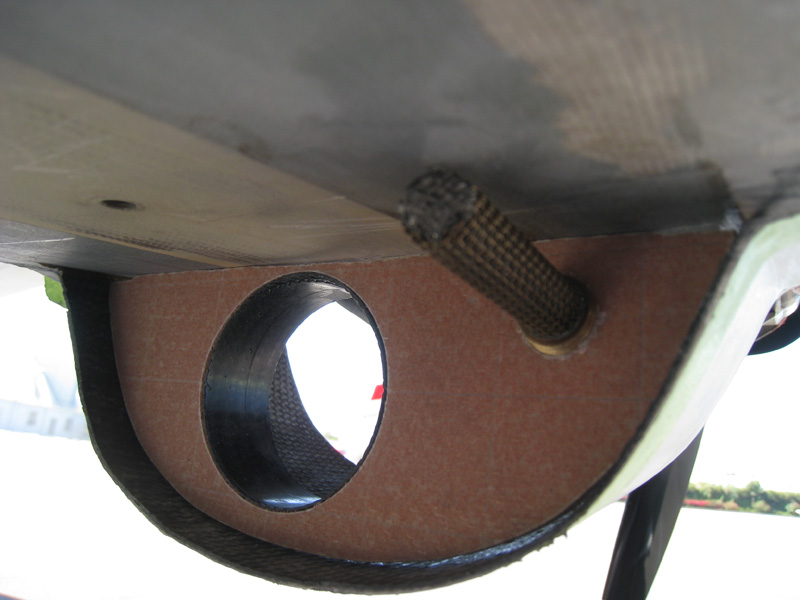
Installation was easy (yeah, right!) - just flox the scoop bulkhead in place, then flox the assembly in place on the bottom of the fuselage, and a BID tape over the lower cowl lip to create the intersection flange. Some micro, lots of upside-down on your back sanding, and some primer and it's installed. Whew!
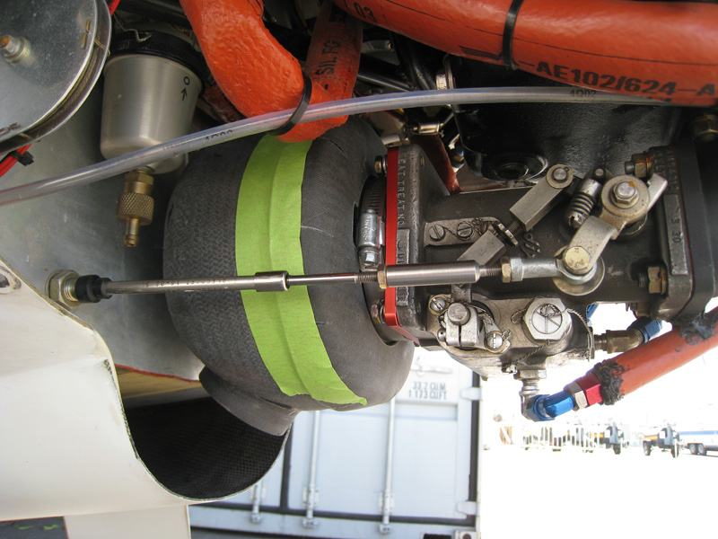
The filter box is connected to the scoop expansion chamber with a SCAT hose with the same diameter as the scoop opening (and servo) and some ring clamps. The injector pressure reference hose is connected to the finger screen pickup via a light-weight -6 flex hose. I took care to position the SCAT hose connection high enough to clear the lower cowl lip when installed and well as not rub on anything when the engine vibrates. The alternate air valves have plenty of room and are not obstructed. The final product is cleanly installed and best of all - WORKS!
I used this configuration for everyday flying and enjoy it's benefits all the time. But for an additional race-day boost, I simply remove the filter box and use a longer SCAT tube to connect the scoop directly to the servo. This gives me an additional .5" MP on top of pressure recovery gains by deleting the filter restriction losses! I routinely see more than 29"MP at T.O. and climb out (hot, high DA day)and have seen 31.5" down low in race config. Yet, it seems to screw up my high cruise LOP ops. I'm not sure why just yet, but this is only a race-day mod anyway. So regardless, this was the most effective mod I have made yet!
This will be a never ending list... Check back soon!
 Back to the Proto-page